Studies on Three-Dimensional (3D) Modeling of UAV Oblique Imagery with the Aid of Loop-Shooting


1
College of Tourism and Geographical Science, Yunnan Normal University, Kunming 650500, China
2
Key Laboratory of Resources and Environmental Remote Sensing for Universities in Yunnan, Kunming 650500, China
3
College of Geography & Environmental Science, Guizhou Normal University, Guiyang 550025, China
4
College of Geographic Science, Nantong University, Nantong 226019, China
*
Author to whom correspondence should be addressed.
ISPRS Int. J. Geo-Inf. 2018, 7(9), 356; https://doi.org/10.3390/ijgi7090356
Submission received: 11 July 2018
/
Revised: 19 August 2018
/
Accepted: 20 August 2018
/
Published: 27 August 2018
Abstract
:Oblique imagery obtained from an Unmanned Aerial Vehicle (UAV) has been widely applied to large-scale three-dimensional (3D) reconstruction; however, the problems of partially missing model details caused by such factors as occlusion, distortion, and airflow, are still not well resolved. In this paper, a loop-shooting-aided technology is used to solve the problem of details loss in the 3D model. The use of loop-shooting technology can effectively compensate for losses caused by occlusion, distortion, or airflow during UAV flight and enhance the 3D model details in large scene- modeling applications. Applying this technology involves two key steps. First, based on the 3D modeling construction process, the missing details of the modeling scene are found. Second, using loop-shooting image sets as the data source, incremental iterative fitting based on aerotriangulation theory is used to compensate for the missing details in the 3D model. The experimental data used in this paper were collected from Yunnan Normal University, Chenggong District, Kunming City, Yunnan Province, China. The experiments demonstrate that loop-shooting significantly improves the aerotriangulation accuracy and effectively compensates for defects during 3D large-scale model reconstruction. In standard-scale distance tests, the average relative accuracy of our modeling algorithm reached 99.87% and achieved good results. Therefore, this technique not only optimizes the model accuracy and ensures model integrity, but also simplifies the process of refining the 3D model. This study can be useful as a reference and as scientific guidance in large-scale stereo measurements, cultural heritage protection, and smart city construction.
1. Introduction
Three-dimensional (3D) modeling of Unmanned Aerial Vehicle (UAV) oblique imagery is an effective approach for displaying geographic information of spatial scenes; its advantages include flexibility, high modeling efficiency and a short production cycle [1,2,3]. Oblique imagery breaks through the limitations of traditional aerial imagery because it obtains abundant oblique images from various perspectives. Consequently, it has been widely applied, and numerous studies have been conducted to investigate 3D modeling based on UAV oblique imagery.
UAV oblique imagery techniques have been applied to 3D modeling in studies of smart cities, farm-house registration, post-disaster building-damage assessments, and archaeology [4,5,6,7,8]. From an overall point of view, 3D model scene reconstruction based on oblique images has good integrity; however, from a local point of view, the modeling result lacks sufficient local details: outliers, distortions and deformities in the source data restrict the accuracy of UAV oblique imagery-based modeling techniques. Thus, many studies have focused on how to repair these deficiencies and compensate for deformities in 3D models of large scenes. Some studies combined close-range photogrammetry with geometric and texture repair to compensate for deficiencies and improve model accuracy [9,10,11]. Other experts also studied the camera calibration method to improve UAV modeling accuracy [12,13]. Experts and scholars have explored various aspects of the model, from hardware to software and from improving a single algorithm to fusing multisource algorithms [14]. In particular, several scholars proposed approaches using Global Navigation Satellite System-/-Inertial Measurement Unit (GNSS/IMU)-aided modeling and skeleton camera network-embedded structure modeling to optimize and improve modeling accuracy [15,16,17]. However, the difficulties of processing multilens images, the complexity of detailed geometry recovery, the high cost of equipment, the limitations of the algorithm, and the time limit of the production workflow have restricted the popularity of such technologies. In response to such problems, Jutzi et al. [18] fused multisource data to construct a 3D model. Henry et al. [19] adopted new RGB-D camera images for 3D modeling. Rhee and Kim [20] improved the method for generating 3D point clouds through a global optimization algorithm that increased point cloud density. These researchers achieved a higher modeling accuracy by avoiding outliers, controlling image accuracy, and improving the modeling process. In summary, although the various available methods can increase the modeling accuracy to some extent and reduce the modeling deficiencies, problems still exist when reconstructing 3D models of geographic scenes, in particular, how to simplify the optimization algorithm that addresses deformity distortion and collapse, and how to ensure that the final model is sufficiently refined. To solve these problems, in this study, a loop-shooting-aided technology is adopted to compensate for the information deficiencies in the collected model scenes. This technology effectively solves the problems that arise from occlusion, distortion, and airflow during the data acquisition stage and enhances the 3D model details in large 3D scene modeling applications. The loop-shooting-aided approach acquires images at 360° around the target object in order to obtain detailed side view information for the objects to be modeled. Thus, using this technology guarantees the integrity of the final 3D modeling product.
This experiment in this study used data collected from the Chenggong campus of Yunnan Normal University, Kunming City, Yunnan Province. To construct a 3D model of the 1.43 km2 area of the campus, loop-shooting-aided technology was used to achieve the goal of building a refined 3D large-scene model. This approach can provide a useful reference and scientific guidance for fields such as stereo measurement, archaeological excavations, and smart cities.
2. Study Area and Data
2.1. Experimental Equipment
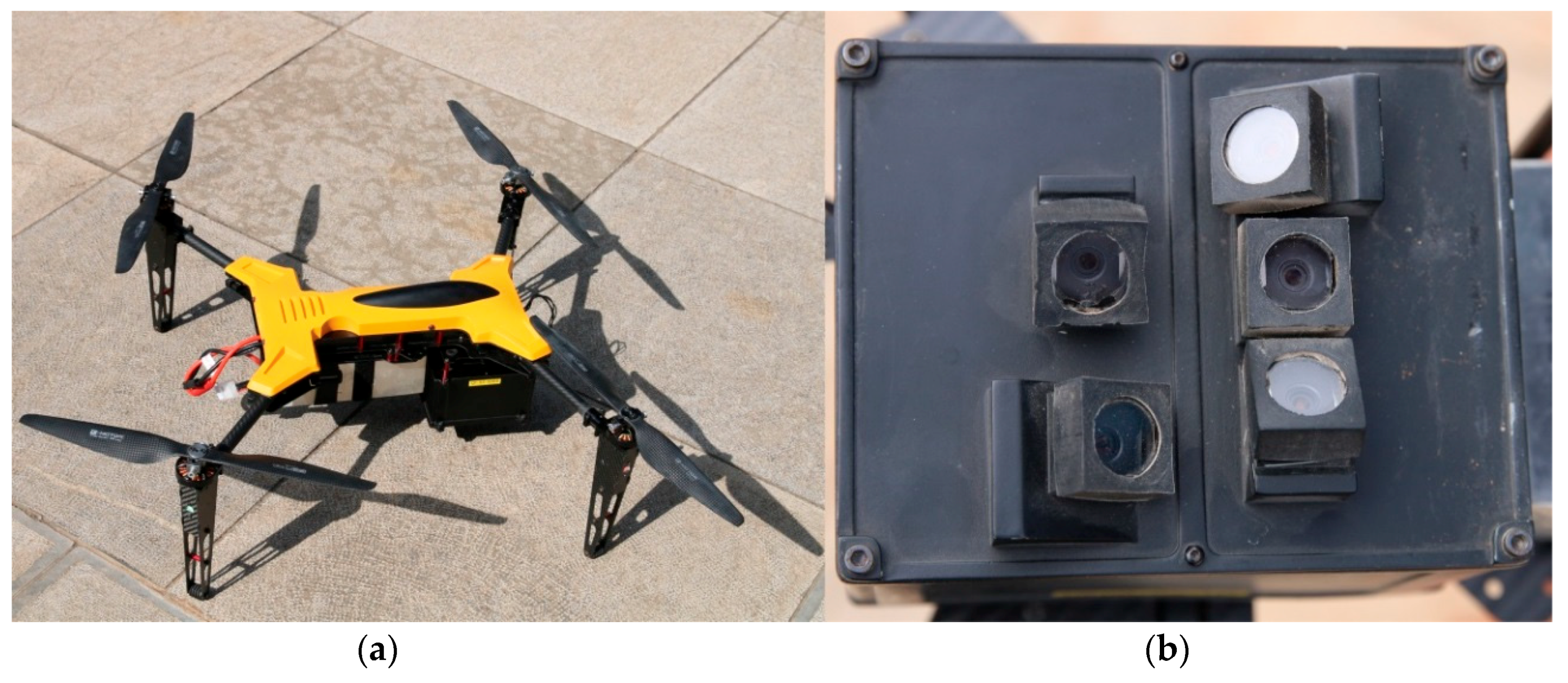
On 23 September 2017, we used a UAV carrying a five-lens camera to collect images in the study area. The five lenses were connected using a fixed device, to avoid error introduced by manual inspection. To ensure the accuracy of the captured image pixels, the five lenses mounted on the UAV had a fixed focus, with a focal length of 16 mm. The UAV configuration is shown in Table 1.
The Chinese made multirotor UAV used in the experiment carries five lenses, as shown in Figure 1. Based on prior research [21,22], UAV-acquired errors can be caused by atmospheric refractions, airflow and the Earth’s topography, leading to radial distortion and tangential distortion errors. Therefore, each camera should be corrected based on calculating the corresponding parameters of radial distortion and tangential distortion, which are often expressed as K1, K2, K3, P1 and P2. Consequently, the UAV cameras were calibrated, and the obtained camera-related parameters are listed in Table 2.
2.2. Description of the Experimental Data
2.2.1. Selection of the Research Area
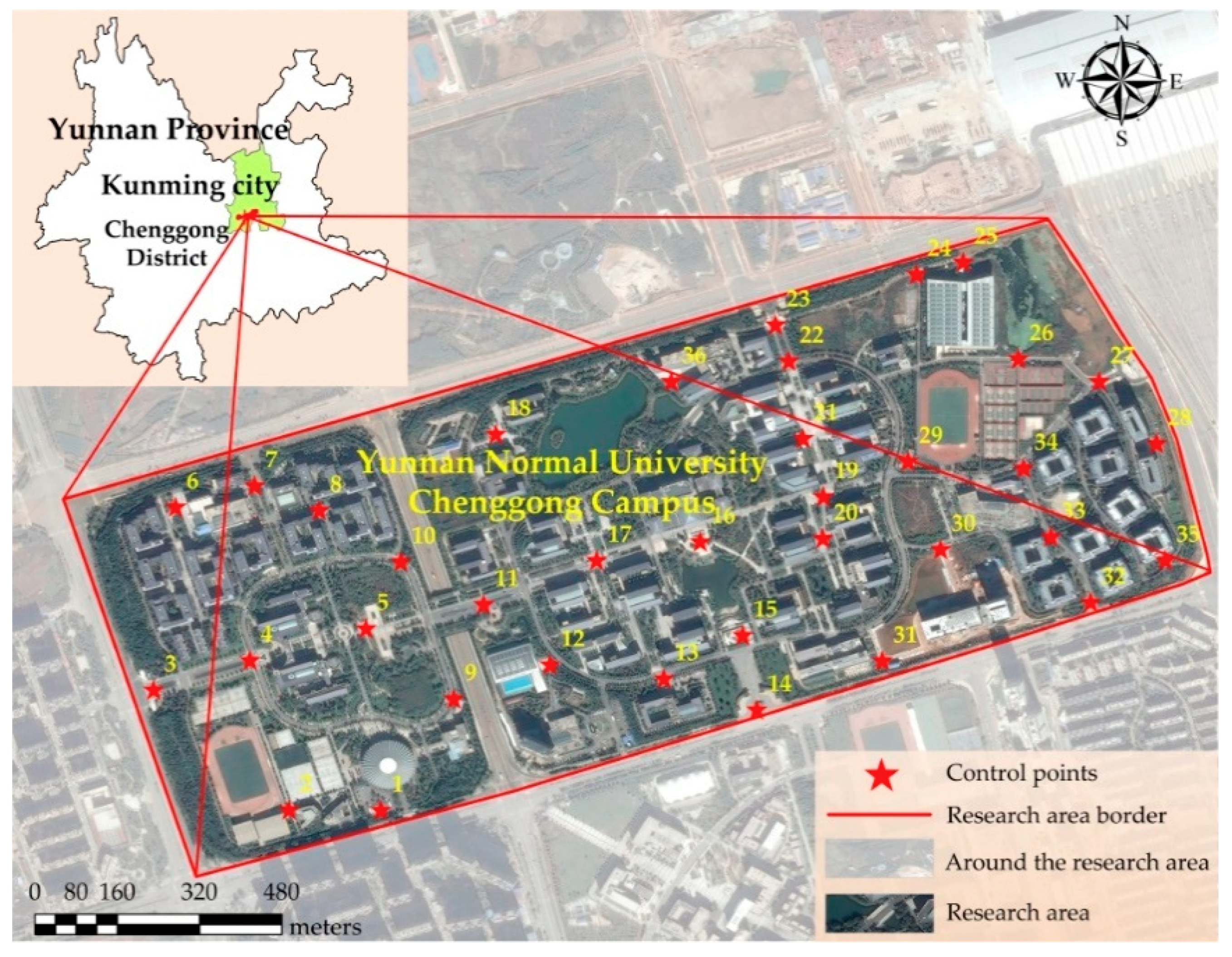
In this paper, we comprehensively take various factors into consideration, including the climate conditions, topographic and geo-morphological conditions, operational feasibility, and human environment. Finally, the Chenggong campus of Yunnan Normal University in Chenggong, New District of Kunming City, Yunnan Province, was selected as the test area for UAV image acquisition. The latitude and longitude at the center of the Chenggong campus of Yunnan Normal University are 24°51′59′′ N and 102°50′58′′ E, respectively. The area covers approximately 1.43 km2, and its average elevation is above 1900 m. The airflow was relatively stable during the photographing process, and the pressure was moderate, which is conducive to acquiring high-quality aerial images. Moreover, the research area has good transportation and an open space far away from the airport and other no-fly zones, which were convenient for UAS equipment transportation, takeoff and landing. In addition, the research area includes rich geospatial features. For example, it includes buildings with various geometrical characteristics and heights, water bodies, vegetation, and roads, which have a universal representation. The research area is shown in Figure 2.
2.2.2. Acquisition of Experimental Data
The average forward overlap of the oblique images obtained by the UAV was 80%, the side overlap was 75%, and the heading direction was southeast-northwest. In total, there were 52 flight routes, and the interval between each flight route was 50 min. The relative flight altitude was 80 m. The ground resolution of the downlooking images was 2 cm, and the average ground resolution of the oblique images was 3 cm. For this experiment, 13 flights were planned, and we obtained 10,257 UAV image frames, including 9457 UAV images and 800 loop-shooting-aided images. We placed 36 ground control points uniformly throughout the research region. The tone of the images was normal, the degree of saturation was moderate, and the pictures were clear and fully compliant with the modeling requirements. Image preprocessing software on the UAV was used to preprocess the 10,257 image frames; the preprocessing operations included blur removal, noise reduction and image enhancement. The camera parameters, focal length, pixel size, and coordinate projection mode of the images were fixed. Finally, Position and Positioning System (POS) data were imported, and rough corrections were performed on the POS data.
3. Methods
3.1. The 3D Modeling Process
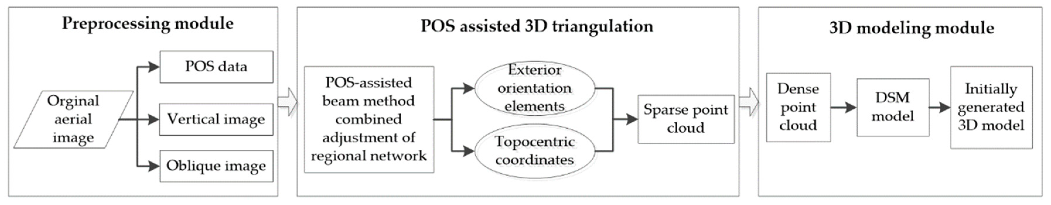
The general 3D modeling process based on UAV oblique imagery technique includes field data acquisition, image preprocessing, aerotriangulation, dense matching, digital surface model (DSM) construction, and texture mapping. In this paper, the 3D modeling process is divided into three modules: a data preprocessing module, a POS-aided aerotriangulation module, and a 3D model construction module, each of which is described as follows. (1) Data preprocessing module: the UAV images are obtained in the field, and image preprocessing is completed (including image denoising, intensification, and rough correction of POS parameters); (2) POS-aided aerotriangulation module: the POS data are taken as the initial values to establish the error equation. The accurate exterior orientation elements of images and topocentric coordinates are calculated by the bundle block adjustment method, which can generate a sparse point cloud. (3) 3D model construction module: Multiview dense matching is performed on the aerotriangulation results to generate a dense point cloud; then, the DSM is established, and textures are mapped to form the initial 3D model. The steps in these three modules are depicted in Figure 3.
3.1.1. Data Preprocessing
Data concerning the study area are collected, and the flight plan is developed. The reference parameters of the coordinate system and elevation are used to clarify the information for the sensors carried by the UAV, including the ground resolution, the image overlap rate, the height and number of flights, and the interval at which images are acquired. The images control points in the survey region are set up in advance. The images from one vertical angle and multiple tilt angles are collected by the multisensor equipment carried by the UAV. The acquired UAV images must be preprocessed. The purpose of preprocessing is to reduce the differences between images, simplify the extraction of image feature points and improve the success rate of the 3D model. Therefore, it is necessary for all images to undergo preprocessing operations such as image denoising and image enhancement. The POS data and parameters are inspected and calibrated. The POS data are acquired from the IMU and GNSS collection. The spatial position data and the attitude parameters of the image are obtained when the UAV takes the images. The UAV used in this experiment carries image preprocessing software that can automatically preprocess the acquired images.
3.1.2. POS-Aided Aerotriangulation
Aerotriangulation is also referred to as 3D triangulation, and it is the key procedure in UAV image processing [23]. The goal of aerotriangulation is to extract the image junctions using some of the ground surface control points to perform image matching and to incorporate the entire region into the Earth coordinate system of known control points. Then, the exterior orientation elements of every image and the ground coordinates of the encryption points are used to generate a sparse point cloud. First, Kalman filtering is applied to the POS data for data fusion; the processed POS data are directly taken as the exterior orientation elements of the image, which act as the initial values for the combined bundle block adjustment. Then, the error equation is established and the normal equation is improved. Based on the ground control points, the cyclic block color histogram [24] approach is used to solve the improved normal equation and obtain high-precision exterior orientation elements and the topocentric coordinates of every picture. A sparse point cloud is constructed using the obtained topocentric coordinates.
3.1.3. Construction of the 3D Model
After generating the sparse point cloud through 3D triangulation, the cluster multiview stereo (CMVS) [25] and patch based multiview stereo (PMVS) algorithms [26] are used to conduct cluster classification and surface calculation of the images. Then, DSM data based on the superhigh-density point clouds of real images are generated. Finally, the texture information is mapped to the DSM, generating the initial 3D model. However, traditional 3D models lack sufficient geographic scene information; hence, they cannot effectively guarantee the integrity of the final model.
3.2. Incremental 3D Modeling with the Aid of Loop-Shooting
In this paper, based on an initially constructed 3D model [27,28,29,30], an incremental 3D model reconstruction method aided by loop-shooting is proposed to ensure model integrity. The applied loop-shooting-aided technology is intended to address the limitations resulting from the lack of 3D model details; this approach compensates for the lack of model scene information through incremental calculations of the images acquired during 360° loop-shooting.
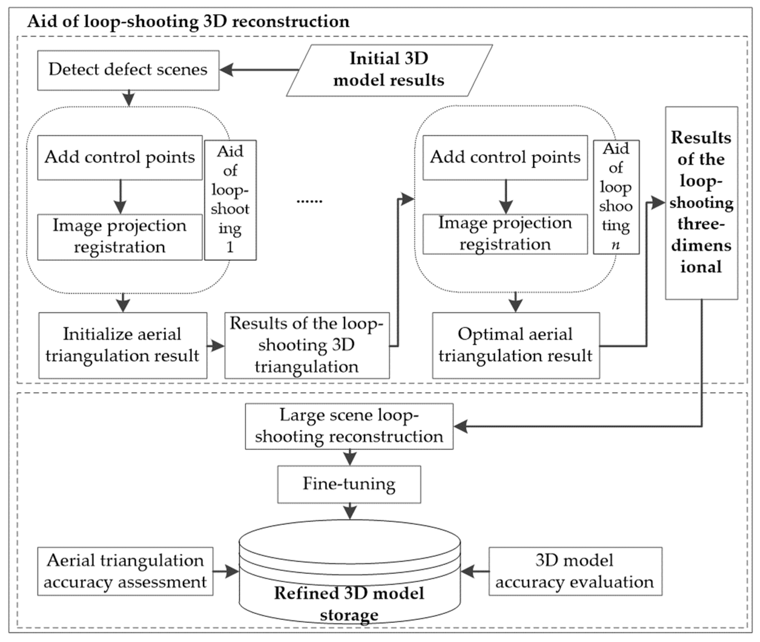
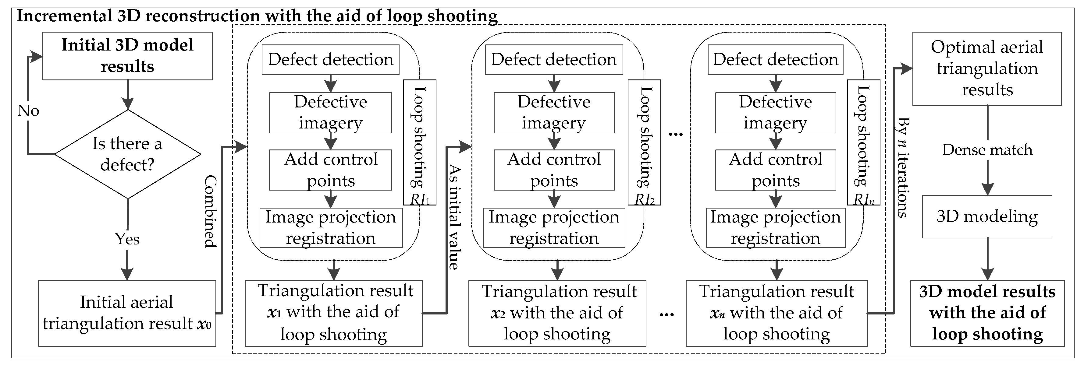
To further elaborate on the mechanism of the incremental 3D reconstruction method with the aid of loop-shooting, the computation is conducted in two parts: incremental 3D modeling with loop assistance and accuracy verification followed by model modification. A flow-chart of the incremental 3D modeling process is shown in Figure 4.
Incremental modeling aided by loop-shooting: In the initial 3D model scene, the missing region of the model is searched and the set of loop-shooting images for the missing region is acquired. The optimal results are then reestablished through iterative incremental fitting based on aerotriangulation theory, using the corresponding model of the missing region.
Accuracy verification and model modification: The accuracy of the 3D reconstruction results aided by loop-shooting is first verified; then, the reconstruction model (including uniform color, tensile, leveling and deletion) is refined, and finally, the completed 3D model is exported.
3.2.1. Incremental Modeling with the Aid of Loop-Shooting
Initially, some details of the 3D model scene are missing. These missing details occur because the image series lacks some of the specific images required to present the complete model scene. The key aspect of loop-shooting-aided reconstruction is to increase the number of point clouds in the detailed parts of the model. The incremental iterative solution is conducted to increase the number of point clouds by combining the loop-shooting image set with the initial aerotriangulation results. At the end of these calculations, the external orientation element and the ground 3D coordinate points under the loop-shooting 3D triangulation (conducted specifically to increase the number of point clouds in the defective region) are obtained. This loop-shooting incremental iterative aerotriangulation process continues until all the defective areas have been repaired, resulting in an optimal reconstructed aerotriangulation to generate the 3D model of the entire scene. The specific procedures are as follows:
Step 1: Detect model defect areas. Based on the initial 3D model, model defect areas (which include occlusions, distortions, and void areas) are detected by the geographic location method [31]. The precise geographical location of each defective region is recorded.
If the scale of the model scene is relatively large, GNSS-aided positioning is adopted. The calculation is shown in the following equation:
where S is the set of all defective regions in the initial model scene and sj is the jth defective region s.
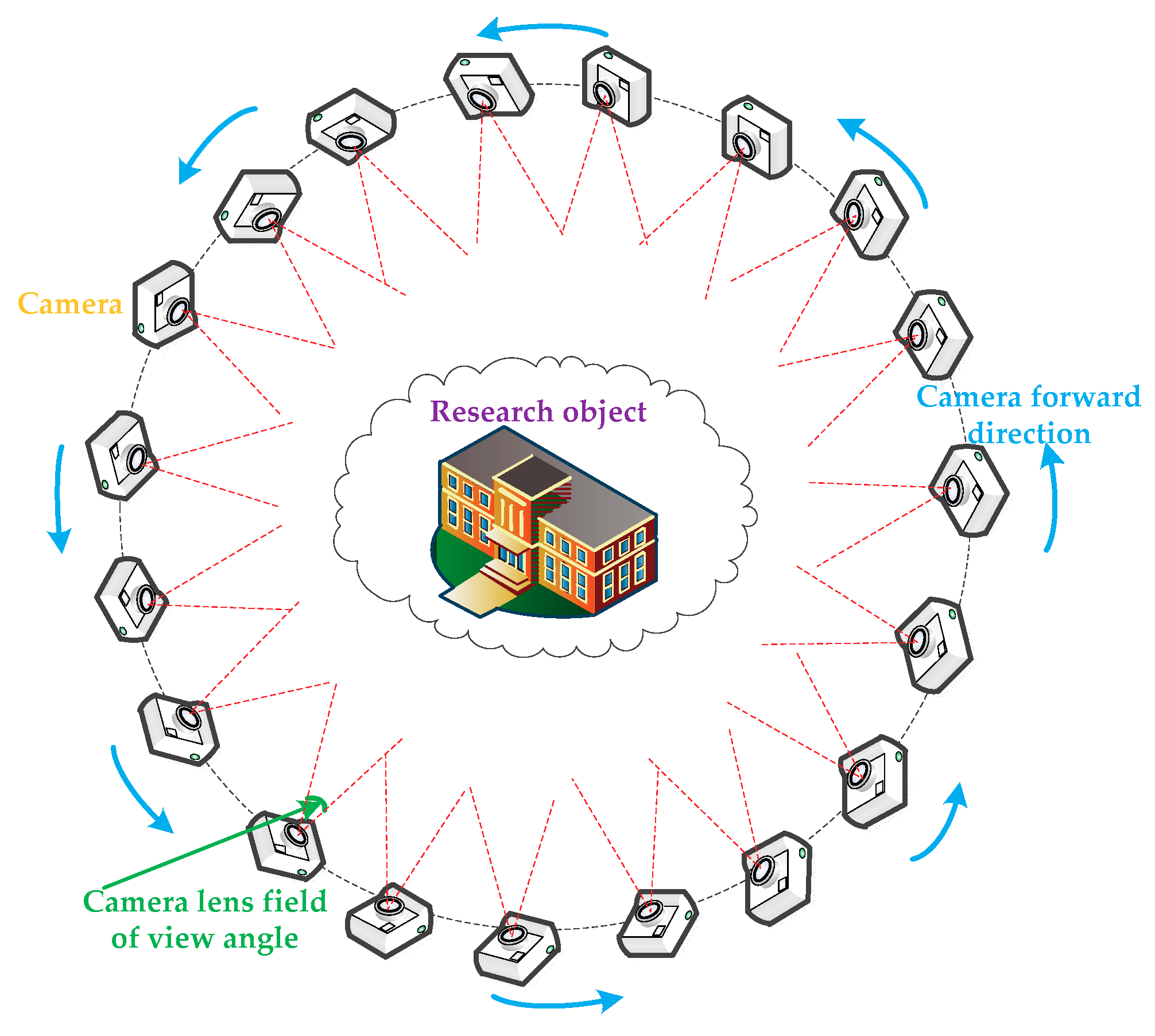
After obtaining all the defective regions S by Equation (1), the loop-shooting images of the defective region are acquired. When acquiring the loop-shooting images, a 360° forward mode is adopted to ensure that the loop-shooting directions are consistent. After the images are taken, the nth loop-shooting image set is denoted as RIn. A schematic flow chart of the loop-shooting process is shown in Figure 5. While acquiring images, the overlap rate must be ensured in every two adjacent images (such as a 75% overlap rate). In addition, the acquisition process must ensure that a sufficient number of matching points will exist between the loop-shooting images and the original UAV images. The specific strategies adopted are as follows: select an image in advance to calculate the corresponding matching points using a threshold of 70% of the total image matching points. Then, determine the matching points of the other loop-shooting images. Image whose matching points exceed the threshold are retained; the others are deleted.
Step 2: Calculate the exterior orientation elements of the loop-shooting images. The geographical spatial location is determined by the selected loop-shooting images. The exterior orientation elements of the loop-shooting images are calculated by space resection [32]. In detail, the relationship between the object space coordinates and the image point coordinates are established by direct linear transformation and the colinear equations are constructed [33]. To solve the collinear equation and obtain the initial external reference values of the loop-shooting images, at least 6 control points are placed in the object space (in this paper, 7 control points are used to solve the collinear equation). The purpose of the collinear equation is to establish the correlation between the ground point, the image point, and the projection center [34,35].
The mathematical expression is as follows:
where (x, y) represents the image point coordinate; (x0, y0) represents the coordinate of the principal point of the image; (X, Y, Z) represents the ground point corresponding to the image point coordinate; (XS, YS, ZS) represents the projection center coordinate; and represents the matrix of the rotation transformation.
After a series of derivation transformations, Equation (2) is calculated as follows:
The coefficients of li can be calculated by the ground control point and the corresponding image point. There are 11 coefficients in Equation (3); therefore, solving it requires a minimum of 6 control points.
After solving Equation (3), to ensure the robustness and precision of the external parameters, the initial external parameters are optimized by the space resection algorithm, whose core purpose is to “extrapolate” the exterior orientation elements of the loop-shooting images through the 3D triangulation results.
Step 3: Update the coordinates of the 3D triangulation results. After adding the loop-shooting images, new matching relationships can be calculated. In other words, after obtaining the exterior orientation elements of the loop-shooting images, the new 3D point coordinates are obtained by a multi-image forward intersection [36]. To improve the reliability of the model points, they are filtered by the size of the intersection angle between all the light rays corresponding to the 3D points. Then, the 3D point coordinates in the region are updated. This process ensures that the 3D triangulation results and the loop-shooting images are both located in the unified coordinate system.
Step 4: Optimize the results of the 3D triangulation. The loop-shooting images, the 3D point coordinates from Step 3, and the initial 3D triangulation results are combined, and the bundle block adjustment method is conducted again to generate a new point cloud. To ensure the accuracy of the results, an incremental adjustment calculation is applied, and the corresponding errors are eliminated after each adjustment.
Specifically, after the new 3D triangulation results are calculated by the bundle block adjustment method, the corresponding errors are eliminated based on the root-mean-square error (RMSE) distribution of the reprojection error. First, the median reprojection errors are set to be the minimum threshold , and the 1.5-fold value of the median is set as the maximum threshold . Then, the RMSE values of the reprojection, T, are statistically analyzed for each image. When T is smaller than , the image is retained, and when T is greater than , the image is discarded. When T is between and , the RMSE of reprojection of the two neighboring images (those directly adjacent to this image) are analyzed to determine whether they are significantly different: When the difference is large, the image is discarded; otherwise, it is retained. After this judgment has been completed, based on the adjusted 3D triangulation results, we continue to conduct the next adjustment calculation until the threshold condition is satisfied. At the end of this process, the loop-shooting image set adjustment is complete, and the process is repeated from Step 1 to Step 4 with the next defective region.
Step 5: Incremental computation to obtain the optimal solution 3D triangulation. After optimizing the results of the 3D triangulation, the set of model defective regions, S, is detected. If the defective regions of the model are not completely repaired, more loop-shooting images are added, and Step 4 is repeated. The mathematical expression for this process is as follows:
where xn is the aerotriangulation result after the nth incremental iterative calculation, is the image set from the nth loop-shooting, and x0 is the initial results of the aerotriangulation.
Through incremental optimization calculation (i.e., Equation (4)), after all the defective regions of the model have been repaired, the results of this loop-shooting 3D triangulation are taken as the optimal 3D triangulation result. Finally, incremental calculations aided by loop-shooting are halted, and the optimal results of the loop-shooting-aided 3D triangulation are saved.
Step 6: The 3D reconstruction of the optimal loop-shooting-aided 3D triangulation. Based on the optimal loop-shooting-aided 3D triangulation results, dense matching is used to construct the DSM model, and textures are mapped to generate the reconstructed 3D model.
A flowchart of the entire loop-shooting-incremental 3D reconstruction process is shown in Figure 6.
3.2.2. Precision Verification and Model Refinement
To evaluate the reliability of the loop-shooting-aided incremental reconstruction method, it is necessary to evaluate its accuracy, which can be verified from the 3D triangulation results and the 3D model results. The verification metrics involve reprojection error, root mean square error in the spatial directions and model deformation. In addition, to better visualize the loop-shooting-aided 3D reconstruction results, a third-party tool is used to fine-tune the scene. In this paper, the third-party tool applied to modify the 3D model reduces color differences in the model scene, removes unnecessary features, and refines them.
4. Experimental Results
4.1. POS-Aided Aerotriangulation Results
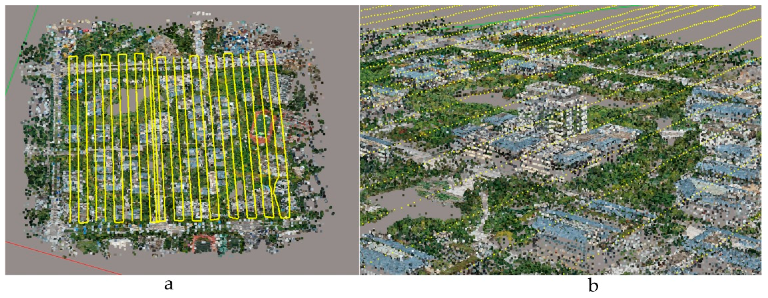
After image preprocessing, the point cloud data of the research area are obtained through aerotriangulation. First, the POS data are fused, and taken as the initial value for the combined bundle block adjustment. Then, various stereo models are connected by relative orientation, and a spatial similarity transformation is used to complete the absolute orientation and obtain high-precision exterior orientation elements and the approximate values of the topocentric coordinates for the pictures. Eventually, sparse point clouds are generated. The initial aerotriangulation results are shown in Figure 7.
4.2. Initial 3D Modeling Results
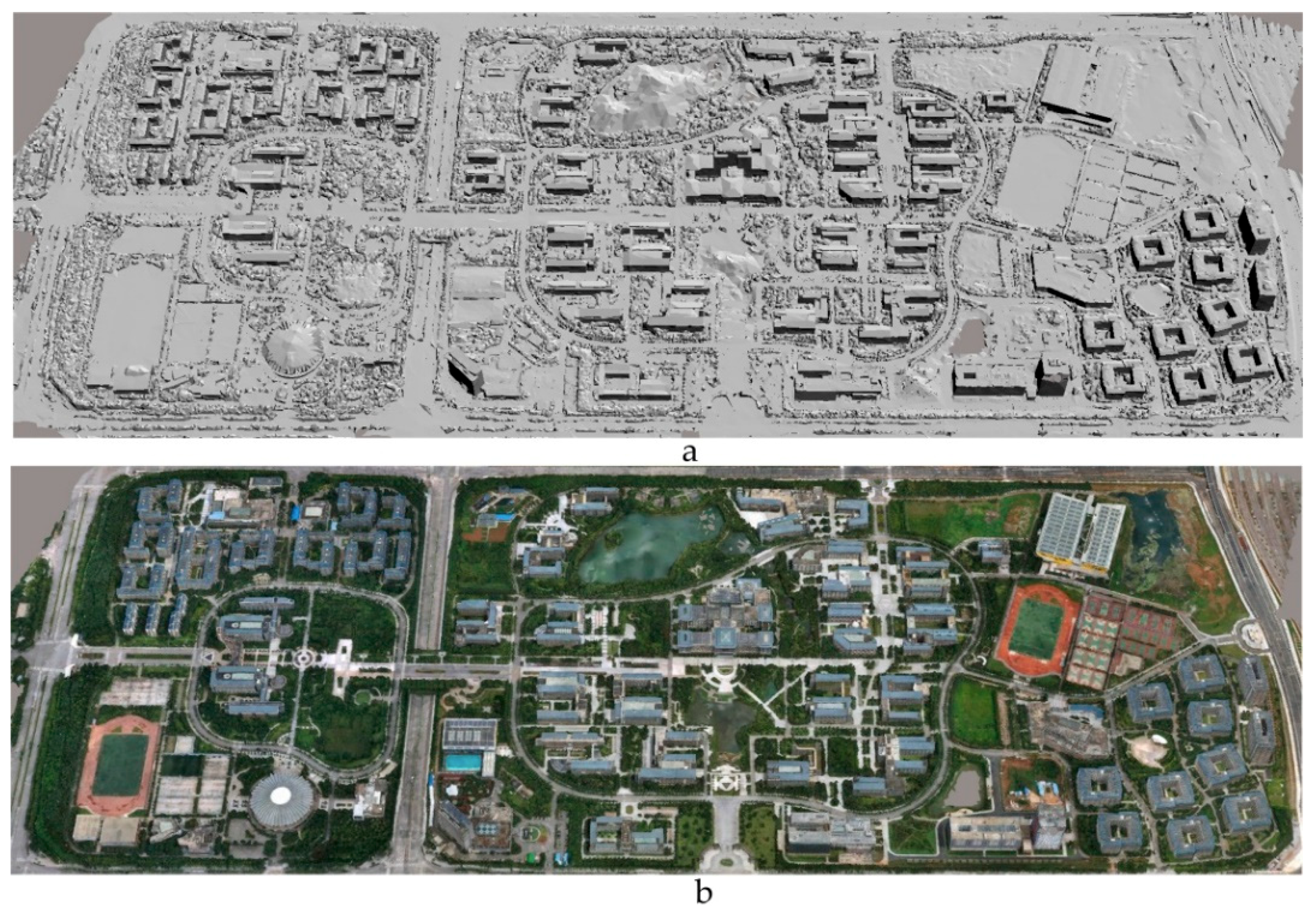
For the 3D triangulation results obtained in the region of Yunnan Normal University, we adopt the CMVS and PMVS algorithms to perform dense matching and generate dense point clouds. Then, the complicated regions on the buildings’ surfaces (such as the gymnasium, swimming pool, and hotels) are processed. Finally, the DSM model of the research region of Yunnan Normal University is constructed, and texture information is projected to generate the initial 3D model, as shown in Figure 8. From observations, the global visual effect of the model in the research area is good. However, the regions occluded by large ground objects or those with limited image photography and complicated buildings still have information defects and distortion phenomena in the model scene. Therefore, increasing the accuracy of the 3D model via loop-shooting is obviously necessary.
4.3. Incremental Modeling with the Aid of Loop-Shooting
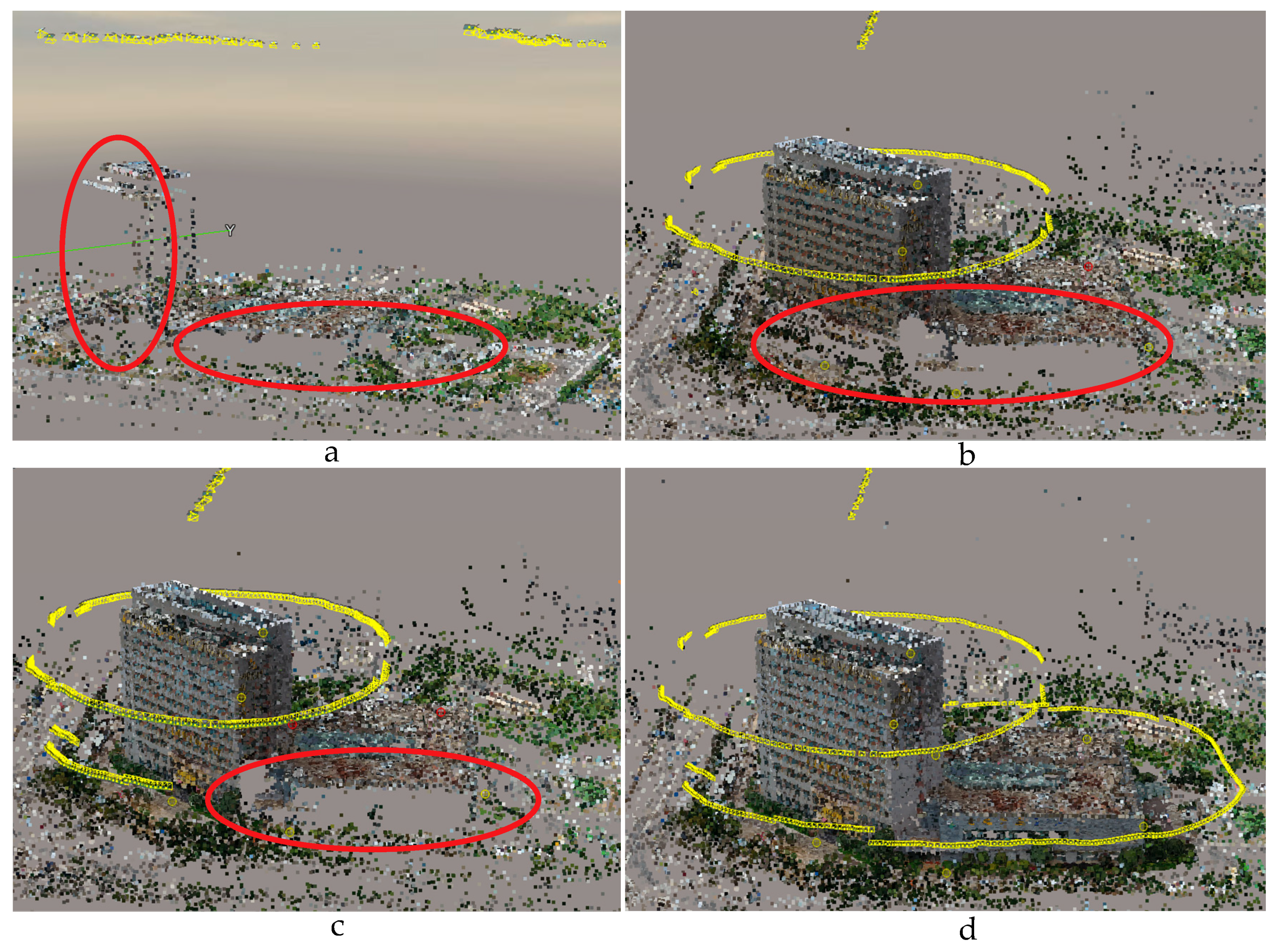
Because the research area of this study is relatively large, the “Fontaine Blanche Hotel” of Yunnan Normal University is selected as an example of the loop-shooting-aided reconstruction results. This example fully represents the optimization process of 3D triangulation and the optimized 3D model reconstruction process; thus, it is convenient for further analysis. After determining the defective regions from the initial 3D model, we conducted several loop-shooting operations on this defective region and obtained abundant images. From the experiment, it can be seen that the inadequate geographic scene information in this region can be augmented through four 3D triangulation optimizations. The results are shown in Figure 9; the defective areas in the images are marked in red.
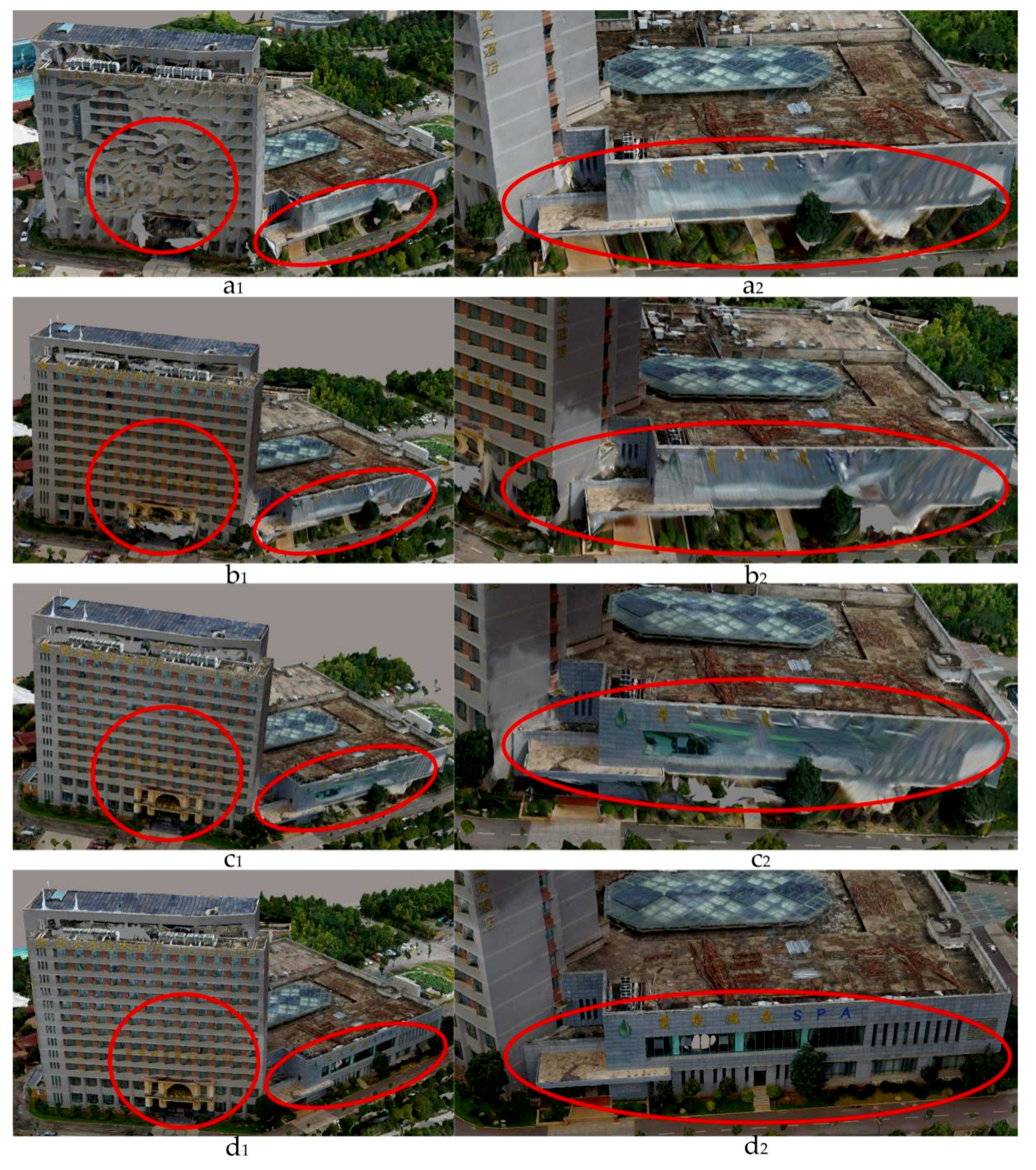
To comprehensively display the effect of 3D modeling assisted by loop-shooting-aided technology, we generated four 3D models corresponding to the four 3D triangulation results to construct views of the “Fontaine Blanche Hotel” of Yunnan Normal University. These four model results are shown in Figure 10. The regions with differences in the figures are marked in red.
4.4. Refined 3D Modeling
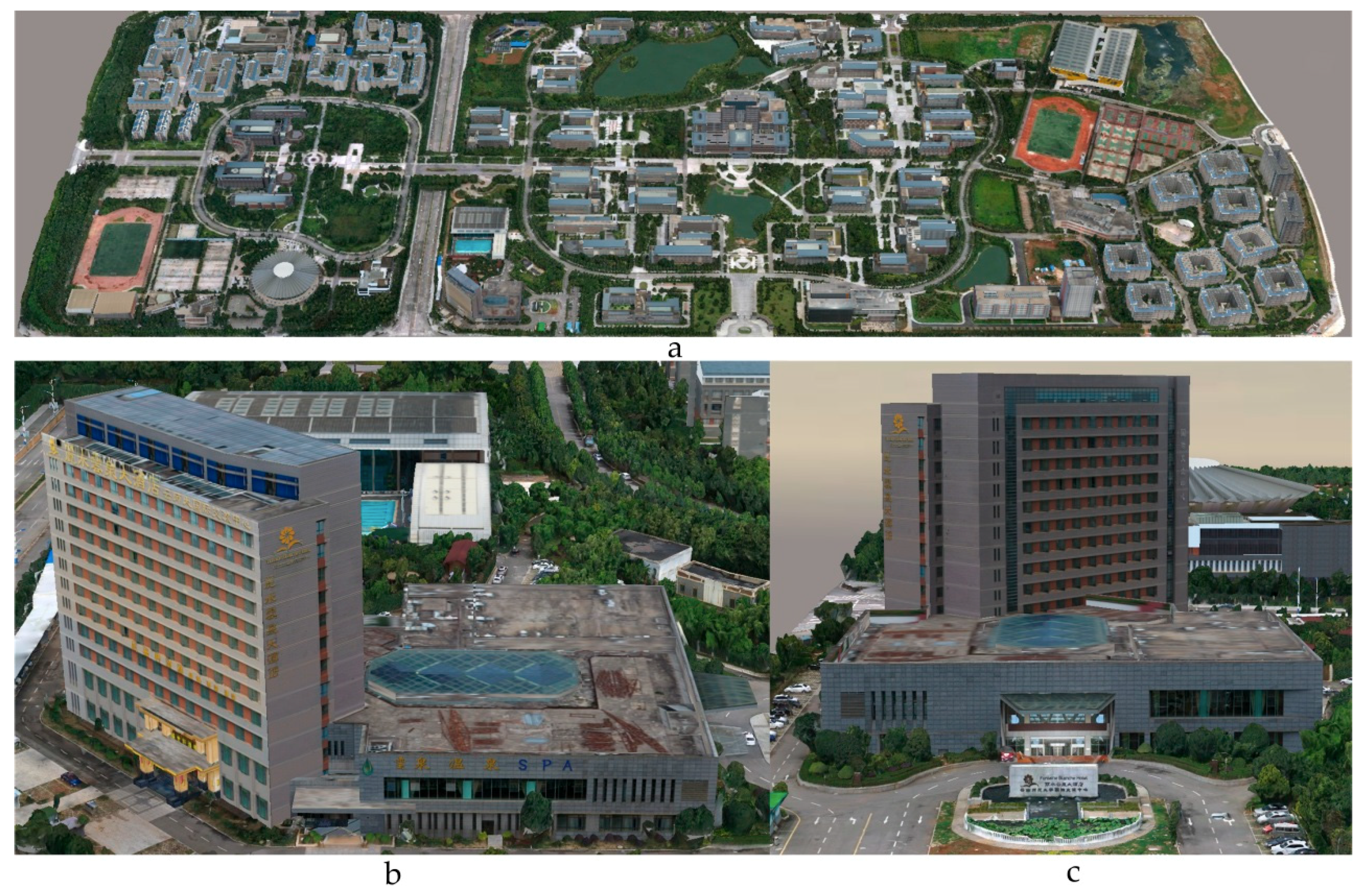
After completing the loop-shooting-aided 3D reconstruction, to better visualize the 3D models, a third-party tool was used to modify the 3D model of Yunnan Normal University. The operations involved smoothing the water surfaces, lawns, roads and parterres. Finally, extra features outside the research area were deleted from the model. Overall, this process improved the effects of all the geographical model scenes, resulting in a more beautiful 3D model of Yunnan Normal University. The results are shown in Figure 11.
5. Discussion
This study adopted a loop-shooting-aided technique to compensate for defects in 3D model scene information caused by occlusions, distortions, and insufficient images. To verify the compensatory effect, experiments were conducted before and after loop-shooting at Yunnan Normal University. The goal of these experiments was to enable the accuracy of the 3D triangulation result before and after loop-shooting to be evaluated based on the errors at the seven control points. Five representative indexes are used to validate the precision: the RMSE of reprojection, the RMSE the distance to rays, the RMSE in 3D space, the RMSE in the horizontal direction, and the RMSE in the vertical direction. To simplify the statistical analyses, we express these indexes as Prj, Dis, 3D, x, and y, respectively, and denote the differences in the indexes before and after loop-shooting by ∆Prj, ∆Dis, ∆3D, ∆x, and ∆y, respectively. The results of the comparisons of these different indexes are shown in Table 3.
At the same time, to fully highlight the overall variations in the accuracy of the loop-shooting-aided 3D triangulation results, we compared them along four aspects: the total number of points, the median number of photos per point, the total RMSE of reprojection, and the RMSE of total distance to rays. For the statistical analyses, these aspects are denoted as All_P, Med_P, All_Prj, and All_Dis respectively. A comparison of the 3D triangulation results is shown in Table 4.
According to Table 3, the accuracy of the seven control points in the loop-shooting-aided 3D triangulation results is usually higher than the accuracy without the aid of loop-shooting. Moreover, as shown by the differences, the five indexes are optimized, which demonstrates that the accuracy of the 3D triangulation results is higher after compensation via loop-shooting. The overall accuracy of the 3D triangulation results in Table 4 indicates that as the number of iterations increases, an obvious change occurs in the total number of points, followed by the change in the median number of photos per point. The total RMSE values of reprojection and of the total distance to rays exhibit a downward trend, further indicating the improvement in the 3D triangulation accuracy.
To enhance the reliability of the loop-shooting-aided method and highlight the integrity of the reconstructed model, after evaluating the 3D triangulation results, the accuracy of the 3D model is further verified both before and after the loop-shooting assistance. After mending, the model distances are compared with the field distances at standard scale distances (the seven distance intervals of 10 m, 20 m, 30 m, 40 m, 50 m, 100 m, and 200 m) to judge the model’s accuracy. At the same time, we also validated the details of the building model repaired with loop-shooting assistance compared to the unrepaired building model. We selected a variety of objects for comparisons (e.g., “doors and windows”, “stairs”, “walls”, and obvious ground objects) to determine the accuracy differences before and after model mending. The results are listed in Table 5 and Table 6.
Table 5 shows the repaired model and the actual measurement values. The model accuracy is usually high, and its relative accuracy is above 99%. The average relative accuracy reaches 99.87%. Table 6 presents a comparison of complicated building details with large deformations and shows that the loop-shooting-aided model achieves considerably higher accuracy than the original model without loop-shooting-aided modeling. In particular, the relative error is usually small, and the relative accuracy reaches 99.14%. The 3D model with loop-shooting-aided results in higher accuracy, smaller errors, and better model integrity, and these effects are obvious.
6. Conclusions
The goal of this paper was to achieve 3D scene modeling reconstruction using UAV oblique imagery with the aid of a loop-shooting technique. The loop-shooting-aided approach can resolve problems stemming from missing detailed information in parts of the model scenes caused by factors such as ground object occlusion, distortion and meteorology and can ensure the integrity of the 3D model. In this paper, for areas of the model with missing scene information, an incremental iterative calculation was performed using the loop-shooting-aided technique to improve the number of points in the sparse point cloud. The optimized 3D model is generated by optimal 3D triangulation calculations through incremental iterative aerotriangulation. This study used the campus of Yunnan Normal University in Kunming City, Yunnan Province, China as an experimental area. The results of experiments show that the loop-shooting-aided approach effectively improves the accuracy of the 3D model. From the accuracy values calculated for the control and junction points, we can see that the results of the loop-shooting-aided 3D triangulation improve the accuracy; the average relative accuracy reached 99.87% through standard-scale distance tests, and the results are good. Therefore, this technique not only effectively improves model accuracy and ensures model integrity but also reduces the difficulty of refining the 3D model. The technique is simple to operate, and its feasibility is high, making it appropriate for rapidly constructing 3D scenes in a regional range. Our approach can be widely applied to various fields, including natural disaster monitoring, 3D scene navigation, cultural heritage protection, and smart city construction, and it can be significant for guiding future scientific efforts.
Our future studies in conducting loop-shooting-aided 3D modeling will focus on further reducing the challenges to model production efficiency during the modeling process and on reducing the generation time.
Author Contributions
J.L. proposed the innovative idea for this paper, performed the research and analyzed the data. Y.Y. and P.D. improved the loop-shooting process and participated in algorithm implementation. S.L. and C.Z. assisted in evaluating the accuracy of the models. Y.C. participated in data collection and data processing. All the authors have read and approved the final manuscript.
Funding
The article is supported by the National Natural Science Foundation of China (No. 41501422), the Yunnan Provincial Department of Education Science Research fund (No. 2018JS148) and the Yunnan Normal University Graduate Research Innovation Fund Project (No. YJS2018107).
Conflicts of Interest
All authors declare no conflict of interest.
References
- Obanawa, H.; Hayakawa, Y.; Gomez, C. 3D Modelling of Inaccessible Areas using UAV-based Aerial Photography and Structure from Motion. Trans. Jpn. Geomorphol. Union 2014, 35, 283–294. [Google Scholar]
- Colomina, I.; Molina, P. Unmanned aerial systems for photogrammetry and remote sensing: A review. ISPRS J. Photogramm. Remote Sens. 2014, 92, 79–97. [Google Scholar] [CrossRef]
- Yang, G.; Liu, J.; Zhao, C.; Li, Z.; Huang, Y.; Yu, H.; Xu, B.; Yang, X.; Zhu, D.; Zhang, X.; et al. Unmanned Aerial Vehicle Remote Sensing for Field-Based Crop Phenotyping: Current Status and Perspectives. Front. Plant Sci. 2017, 8, 1111. [Google Scholar] [CrossRef] [PubMed]
- Menouar, H.; Guvenc, I.; Akkaya, K.; Uluagac, A.S.; Kadri, A.; Tuncer, A. UAV-Enabled Intelligent Transportation Systems for the Smart City: Applications and Challenges. IEEE Commun. Mag. 2017, 55, 22–28. [Google Scholar] [CrossRef]
- Cunningham, K.; Walker, G.; Stahlke, E.; Wilson, R. Cadastral Audit and Assessments Using Unmanned Aerial Systems. ISPRS Int. Arch. Photogramm. Remote Sens. Spat. Inf. Sci. 2012, 3822, 213–216. [Google Scholar] [CrossRef]
- Ham, Y.; Han, K.K.; Lin, J.J.; Golparvar-Fard, M. Visual monitoring of civil infrastructure systems via camera-equipped Unmanned Aerial Vehicles (UAVs): A review of related works. Vis. Eng. 2016, 4, 1. [Google Scholar] [CrossRef]
- Kakooei, M.; Baleghi, Y. Fusion of satellite, aircraft, and UAV data for automatic disaster damage assessment. Int. J. Remote Sens. 2017, 38, 2511–2534. [Google Scholar] [CrossRef]
- Brutto, M.L.; Borruso, A.; D’argenio, A. UAV systems for photogrammetric data acquisition of archaeological sites. Int. J. Herit. Digit. Era 2012, 1, 7–13. [Google Scholar] [CrossRef] [Green Version]
- Room, M.H.M.; Ahmad, A. Mapping of river model using close range photogrammetry technique and unmanned aerial vehicle system. In Proceedings of the 8th International Symposium on Digital Earth, Sarawak, Malaysia, 26–29 August 2013. [Google Scholar]
- Xu, Z.; Wu, L.; Chen, S.; Wang, R.; Li, F.; Wang, Q. Extraction of Image Topological Graph for Recovering the Scene Geometry from UAV Collections. ISPRS Int. Arch. Photogramm. Remote Sens. Spat. Inf. Sci. 2014, 40, 319–323. [Google Scholar] [CrossRef]
- Gui, D.Z.; Lin, Z.J.; Zhang, C.C.; Zhi, X.D. Automated texture mapping of 3D city models with images of wide-angle and light small combined digital camera system for UAV. In Proceedings of the SPIE-The International Society for Optical Engineering, Yichang, China, 30 October–1 November 2009; pp. 74982A-1–74982A-8. [Google Scholar]
- Shang, Y.; Sun, X.; Yang, X.; Wang, X.; Yu, Q. A camera calibration method for large field optical measurement. Optik Int. J. Light Electron Opt. 2013, 124, 6553–6558. [Google Scholar] [CrossRef]
- Yusoff, A.R.; Ariff, M.F.M.; Idris, K.M.; Majid, Z.; Chong, A.K. Camera Calibration Accuracy at Different Uav Flying Heights. ISPRS Int. Arch. Photogramm. Remote Sens. Spat. Inf. Sci. 2017, 42, 595–600. [Google Scholar] [CrossRef]
- Nex, F.; Remondino, F. UAV for 3D mapping applications: A review. Appl. Geomat. 2014, 6, 1–15. [Google Scholar] [CrossRef]
- Jiang, S.; Jiang, W. On-Board GNSS/IMU Assisted Feature Extraction and Matching for Oblique UAV Images. Remote Sens. 2017, 9, 813. [Google Scholar] [CrossRef]
- Xu, Z.; Wu, L.; Gerke, M.; Wang, R.; Yang, H. Skeletal camera network embedded structure-from-motion for 3D scene reconstruction from UAV images. ISPRS J. Photogramm. Remote Sens. 2016, 121, 113–127. [Google Scholar] [CrossRef]
- Tong, X.; Liu, X.; Chen, P.; Liu, S.; Luan, K.; Li, L.; Liu, S.; Liu, X.; Xie, H.; Jin, Y.; et al. Integration of UAV-Based Photogrammetry and Terrestrial Laser Scanning for the Three-Dimensional Mapping and Monitoring of Open-Pit Mine Areas. Remote Sens. 2015, 7, 6635–6662. [Google Scholar] [CrossRef] [Green Version]
- Jutzi, B.; Weinmann, M.; Meidow, J. Weighted data fusion for UAV-borne 3D mapping with camera and line laser scanner. Int. J. Image Data Fusion 2014, 5, 226–243. [Google Scholar] [CrossRef]
- Henry, P.; Krainin, M.; Herbst, E.; Ren, X.; Fox, D. RGB-D mapping: Using Kinect-style depth cameras for dense 3D modeling of indoor environments. Int. J. Robot. Res. 2012, 31, 647–663. [Google Scholar] [CrossRef] [Green Version]
- Rhee, S.; Kim, T. Dense 3D Point Cloud Generation from Uav Images from Image Matching and Global Optimazation. ISPRS Int. Arch. Photogramm. Remote Sens. Spat. Inf. Sci. 2016, 41, 1005–1009. [Google Scholar] [CrossRef]
- Gonçalves, J.A.; Henriques, R. UAV photogrammetry for topographic monitoring of coastal areas. ISPRS J. Photogramm. Remote Sens. 2015, 104, 101–111. [Google Scholar] [CrossRef]
- Remondino, F.; Fraser, C. Digital camera calibration methods: Considerations and comparisons. Int. Arch. Photogramm. Remote Sens. Spat. Inf. Sci. 2006, 36, 266–272. [Google Scholar]
- Ackermann, F. Application of GPS for aerial triangulation. Photogramm. Eng. Remote Sens. 1993, 59, 1625–1632. [Google Scholar]
- Beck, A.; Pauwels, E.; Sabach, S. The Cyclic Block Conditional Gradient Method for Convex Optimization Problems. SIAM J. Optim. 2015, 25, 2024–2049. [Google Scholar] [CrossRef] [Green Version]
- Harwin, S.; Lucieer, A. Assessing the Accuracy of Georeferenced Point Clouds Produced via Multi-View Stereopsis from Unmanned Aerial Vehicle (UAV) Imagery. Remote Sens. 2012, 4, 1573–1599. [Google Scholar] [CrossRef] [Green Version]
- Xiao, X.; Guo, B.; Li, D.; Li, L.; Yang, N.; Liu, J.; Zhang, P.; Peng, Z. Multi-View Stereo Matching Based on Self-Adaptive Patch and Image Grouping for Multiple Unmanned Aerial Vehicle Imagery. Remote Sens. 2016, 8, 89. [Google Scholar] [CrossRef]
- Vacca, G.; Dessì, A.; Sacco, A. The Use of Nadir and Oblique UAV Images for Building Knowledge. ISPRS Int. J. Geo-Inf. 2017, 6, 393. [Google Scholar] [CrossRef]
- Papakonstantinou, A.; Topouzelis, K.; Pavlogeorgatos, G. Coastline zones identification and 3D coastal mapping using UAV spatial data. ISPRS Int. J. Geo-Inf. 2016, 5, 75. [Google Scholar] [CrossRef]
- Saeedi, S.; Liang, S.; Graham, D.; Lokuta, M.F.; Mostafavi, M.A. Overview of the OGC CDB Standard for 3D Synthetic Environment Modeling and Simulation. ISPRS Int. J. Geo-Inf. 2017, 6, 306. [Google Scholar] [CrossRef]
- Zhang, Y.; Yuan, X.; Fang, Y.; Chen, S. UAV low altitude photogrammetry for power line inspection. ISPRS Int. J. Geo-Inf. 2017, 6, 14. [Google Scholar] [CrossRef]
- Djuknic, G.M.; Richton, R.E. Geolocation and assisted GPS. Computer 2001, 34, 123–125. [Google Scholar] [CrossRef]
- Easa, S.M. Space resection in photogrammetry using collinearity condition without linearisation. Emp. Surv. Rev. 2010, 42, 40–49. [Google Scholar] [CrossRef]
- Přibyl, B.; Zemčík, P.; Čadík, M. Absolute Pose Estimation from Line Correspondences using Direct Linear Transformation. Comput. Vis. Image Underst. 2017, 161, 130–144. [Google Scholar] [CrossRef]
- El-Manadili, Y.; Novak, K. Precision rectification of SPOT imagery using the direct linear transformation model. Photogramm. Eng. Remote Sens. 1996, 62, 67–72. [Google Scholar]
- Yan, L.; Gou, Z.Y.; Zhao, S.H.; Su, M.D. Geometric and automatic mosaic method with collinear equation for aviation twice-imaging data. Int. Arch. Photogramm. Remote Sens. Spat. Inf. Sci. 2008, 37, 585–588. [Google Scholar]
- Zhang, Z.; Zhu, L.; Huang, X.; Lai, H.; Zhao, T. Five-Point Relative Orientation Based on Forward Intersection. Acta Opt. Sin. 2015, 35, 231–238. [Google Scholar] [CrossRef]
Figure 1.
(a) is a multirotor unmanned aerial vehicle; (b) is a five-lens camera carried by the UAV.
Figure 1.
(a) is a multirotor unmanned aerial vehicle; (b) is a five-lens camera carried by the UAV.

Figure 2.
Research area map.

Figure 3.
The 3D modeling flowchart.

Figure 4.
Flowchart of incremental 3D modeling aided by loop-shooting.

Figure 5.
Loop-shooting diagram.

Figure 6.
Detailed flowchart of 3D reconstruction aided by loop-shooting.

Figure 7.
(a) The 3D triangulation results for part of the region; (b) Zoomed-in 3D triangulation results.
Figure 7.
(a) The 3D triangulation results for part of the region; (b) Zoomed-in 3D triangulation results.

Figure 8.
(a) Original digital surface model (DSM); (b) Initial 3D model after performing texture mapping.
Figure 8.
(a) Original digital surface model (DSM); (b) Initial 3D model after performing texture mapping.

Figure 9.
(a–d) Representations of the aerotriangulation results aided by varying levels of loop-shooting.
Figure 9.
(a–d) Representations of the aerotriangulation results aided by varying levels of loop-shooting.

Figure 10.
The 3D model results for the “Fontaine Blanche Hotel:” (a) the overall and regional 3D results for the original model; (b) the overall and regional 3D results aided by one loop-shooting operation; (c) the overall and regional 3D results aided by a second loop-shooting operation; and (d) the overall and regional 3D results aided by a third loop-shooting operation.”.

Figure 11.
Final results: (a) the refined model for the entire research region; (b) the refined model for the side of the “Fontaine Blanche Hotel”; (c) the refined model for the front of the “Fontaine Blanche Hotel”.
Figure 11.
Final results: (a) the refined model for the entire research region; (b) the refined model for the side of the “Fontaine Blanche Hotel”; (c) the refined model for the front of the “Fontaine Blanche Hotel”.


Table 1.
Unmanned Aerial Vehicle (UAV) configuration.
| Flight Platform | UAV Configuration |
|---|---|
| Focal length | 16 mm |
| Image pixels | 4000 × 6000 |
| Main point (x, y) | (2999.5, 1999.5) |
| Pixel size | 4 μm |
| Camera sensor | CCD |
| Number of shots | 4 tilted lenses, 1 vertical lens |
| Lens tilt angle | 45° |
Table 2.
Parameter information after UAVcamera calibration.
| Camera | Parameters Symbol | Value |
|---|---|---|
| Focal length (mm) | F | 16 |
| Radial distortion (mm) | K1 | −2.93279097580502 × 10⁻¹⁰ |
| Radial distortion (mm) | K2 | 2.71144019108787 × 10⁻¹⁷ |
| Radial distortion (mm) | K3 | −7.632447492096 × 10⁻²⁶ |
| Tangential distortion (mm) | P1 | −1.0747635629201 × 10⁻¹⁰ |
| Tangential distortion (mm) | P2 | −5.08835248657514 × 10⁻¹¹ |
Table 3.
Results of the comparison of different indexes of the 3D triangulation before and after compensation loop-shooting.
Table 3.
Results of the comparison of different indexes of the 3D triangulation before and after compensation loop-shooting.
| Type | Prj (px) | Dis (m) | 3D (m) | X (m) | Y (m) | ∆Prj (px) | ∆Dis (m) | ∆3D (m) | ∆x (m) | ∆y (m) | |
|---|---|---|---|---|---|---|---|---|---|---|---|
| 1 | Original | 0.1 | 0.002 | 0.004 | 0.002 | −0.004 | −0.16 | −0.001 | −0.002 | 0 | −0.001 |
| 1 | Loop-shooting | 0.26 | 0.003 | 0.006 | 0.002 | −0.005 | |||||
| 2 | Original | 0.5 | 0.014 | 0.017 | 0.014 | 0.01 | 0.05 | 0.005 | 0.003 | 0.005 | 0 |
| 2 | Loop-shooting | 0.45 | 0.009 | 0.014 | 0.009 | 0.01 | |||||
| 3 | Original | 0.88 | 0.021 | 0.021 | 0.005 | −0.021 | 0.08 | 0.01 | 0.009 | −0.004 | 0.013 |
| 3 | Loop-shooting | 0.8 | 0.011 | 0.012 | 0.009 | −0.008 | |||||
| 4 | Original | 0.67 | 0.012 | 0.016 | 0.003 | 0.016 | 0.2 | 0.004 | 0.006 | −0.006 | 0.012 |
| 4 | Loop-shooting | 0.47 | 0.008 | 0.01 | 0.009 | 0.004 | |||||
| 5 | Original | 0.07 | 0.002 | 0.002 | 0.002 | 0 | −0.34 | −0.003 | −0.005 | 0.001 | 0.005 |
| 5 | Loop-shooting | 0.41 | 0.005 | 0.007 | 0.001 | −0.007 | |||||
| 6 | Original | 0.27 | 0.007 | 0.008 | 0.007 | 0.002 | −0.49 | 0.001 | 0.002 | 0.003 | −0.003 |
| 6 | Loop-shooting | 0.76 | 0.006 | 0.006 | 0.004 | 0.005 | |||||
| 7 | Original | 0.49 | 0.012 | 0.013 | 0.011 | −0.006 | 0.22 | 0.008 | 0.007 | 0.006 | 0.003 |
| 7 | Loop-shooting | 0.27 | 0.004 | 0.006 | 0.005 | −0.003 |
Table 4.
Accuracy comparison of the four 3D triangulation results.
| Number | ALL_P | Med_P | All_Prj (px) | All_Dis (m) |
|---|---|---|---|---|
| 1 | 24,477 | 1,069 | 0.71 | 0.018 |
| 2 | 67,442 | 1,060 | 0.69 | 0.019 |
| 3 | 86,204 | 1,170 | 0.68 | 0.017 |
| 4 | 161,145 | 1,371 | 0.69 | 0.016 |
Table 5.
Model observation error and relative accuracy under the standard scale.
| 10 (m) | 20 (m) | 30 (m) | 40 (m) | 50 (m) | 100 (m) | 200 (m) | |
|---|---|---|---|---|---|---|---|
| Observation distance (m) after mending (m) | 10.02 | 20.3 | 30.09 | 40.04 | 50.03 | 100.07 | 200.12 |
| Error value (m) | 0.02 | 0.03 | 0.09 | 0.04 | 0.03 | 0.07 | 0.12 |
| Relative accuracy (%) | 99.80 | 99.85 | 99.70 | 99.90 | 99.94 | 99.93 | 99.94 |
Table 6.
Error and relative accuracy of detailed observations before and after the loop-shooting-aided model reconstruction.
Table 6.
Error and relative accuracy of detailed observations before and after the loop-shooting-aided model reconstruction.
| Small Window | Front Door | Footstep | Back Door | French Window | Stone Pillar | Side Door | |
|---|---|---|---|---|---|---|---|
| Field observation distance (m) | 2.75 | 15.38 | 15.93 | 4.23 | 6.39 | 1.32 | 6.41 |
| Observation distance before mending (m) | 2.65 | 15.22 | 15.86 | 4.11 | 6.14 | 1.22 | 6.52 |
| Observation distance after mending (m) | 2.73 | 15.34 | 15.91 | 4.20 | 6.26 | 1.30 | 6.37 |
| Error value before mending (m) | 0.10 | 0.16 | 0.07 | 0.12 | 0.25 | 0.10 | 0.11 |
| Error value after mending (m) | 0.02 | 0.04 | 0.02 | 0.03 | 0.13 | 0.02 | 0.04 |
| Relative accuracy (%) | 99.27 | 99.74 | 99.87 | 99.29 | 97.97 | 98.48 | 99.38 |
© 2018 by the authors. Licensee MDPI, Basel, Switzerland. This article is an open access article distributed under the terms and conditions of the Creative Commons Attribution (CC BY) license (http://creativecommons.org/licenses/by/4.0/).
Share and Cite
MDPI and ACS Style
Li, J.; Yao, Y.; Duan, P.; Chen, Y.; Li, S.; Zhang, C. Studies on Three-Dimensional (3D) Modeling of UAV Oblique Imagery with the Aid of Loop-Shooting. ISPRS Int. J. Geo-Inf. 2018, 7, 356. https://doi.org/10.3390/ijgi7090356
AMA Style
Li J, Yao Y, Duan P, Chen Y, Li S, Zhang C. Studies on Three-Dimensional (3D) Modeling of UAV Oblique Imagery with the Aid of Loop-Shooting. ISPRS International Journal of Geo-Information. 2018; 7(9):356. https://doi.org/10.3390/ijgi7090356
Chicago/Turabian StyleLi, Jia, Yongxiang Yao, Ping Duan, Yun Chen, Shuang Li, and Chi Zhang. 2018. "Studies on Three-Dimensional (3D) Modeling of UAV Oblique Imagery with the Aid of Loop-Shooting" ISPRS International Journal of Geo-Information 7, no. 9: 356. https://doi.org/10.3390/ijgi7090356
Note that from the first issue of 2016, this journal uses article numbers instead of page numbers. See further details here.