Graphite Optics—Current Opportunities, Properties and Limits

Optigraph GmbH, Rudower Chaussee 29, 12489 Berlin, Germany
*
Author to whom correspondence should be addressed.
Condens. Matter 2019, 4(1), 18; https://doi.org/10.3390/condmat4010018
Submission received: 21 November 2018
/
Revised: 11 January 2019
/
Accepted: 21 January 2019
/
Published: 24 January 2019
(This article belongs to the Special Issue High Precision X-Ray Measurements)
Abstract
:X-ray graphite optics consists of thin layers of Pyrolytic Graphite (PG) attached to a substrate of focusing shape. Pyrolytic Graphite is a perfect artificial graphite obtained by annealing of carbon deposit at temperatures about 3000 °C under deformation. By varying the annealing conditions, one could get PG of different mosaic structure and mechanical properties. A wide variability of the reflecting layer characteristics and optics shape makes the graphite optics useful in an extended range of applications. The optics could be adjusted to applications that require moderate resolution as EDXRF (energy dispersive X-Ray fluorescence) and as well as for high-resolution applications as EXAFS (extended X-ray absorption fine structure), XANES (X-ray absorption near-edge structure) and XES (X-ray emission spectroscopy). To realize the optics with theoretically optimized parameters the relationship between the production procedure and the mosaicity and reflectivity of the optics was experimentally studied. The influence of thickness, the type of PG (Highly Oriented PG (HOPG) or Highly Annealed PG (HAPG)) and substrate characteristics on the optics performance is presented.
1. Introduction
The recent interest in the fine structure of spectra [1], low probability events [2] and low concentrations [3] accompanied with the requirement for decreased X-ray environmental impact of the source generates the needs in efficient X-ray optics. Capillary and multilayers, ideal crystals and many other devices are in use, each has its advantages and restrictions. Graphite Optics (GrO)—one of the brightest variants of X-ray optics becomes more and more popular, especially since Highly Annealed Pyrolytic Graphite (HAPG) with mosaic spread of 0.1° was created.
Due to the wide variability of the reflecting layer and of the optics shape, the GrO could be used in enlarged number of applications. The optics is helpful for applications requiring moderate energy resolution as well as for high-resolution applications.
A typical application where GrO is in use for more than 20 years is EDXRF (energy dispersive X-Ray fluorescence). The optics serves as monochromator and focusing device for the primary beam as well as a broadband filter between sample and detector. GrO as a broadband filter is essential for the detection of trace elements in heavy matrix [4] or the element under investigation in the presence of interfering element [5]. For this application, Highly Oriented Pyrolytic Graphite (HOPG optics with moderate energy resolution and good flux is more popular; however, recently, HAPG optics with improved mosaicity and better energy resolution has also been in use. Doubly curved short focus GrO of both types is exploited in commercial set-up [6].
In high resolution applications HAPG optics is used in von Hamos geometry as an effective dispersive element for X-ray absorption and emission spectroscopy. The efficiency of spectrometers based on HAPG optics makes it possible to implement the methods usually requiring Synchrotron Radiation (SR) sources such as XES (X-ray emission spectroscopy) and XAFS (X-ray absorption fine structure) at low brilliant laboratory sources [1,7]. HAPG optics is used in the first commercial X-ray absorption spectroscopy system QuantumLeap-XAS by Sigray [8].
Plasma analysis is another application field where GrO-based spectrometers characterize the temperature, density and ionization stage of warm dense plasma [9]. High thermal and radiation stability is a key advantage of GrO for the application. The optics is able to work in high fluencies of neutrons and laser-plasma debris.
For each application, a certain form of PG could be chosen and then the characteristics of the reflecting layer could be additionally tuned.
2. Properties and Structural Peculiarities of the Reflecting Layer in Graphite Optics
Graphite Optics produced by Optigraph GmbH [10] consists of a layer of Pyrolytic Graphite (PG) deposited on a substrate of required shape. The layer could be up to a few hundred microns thick.
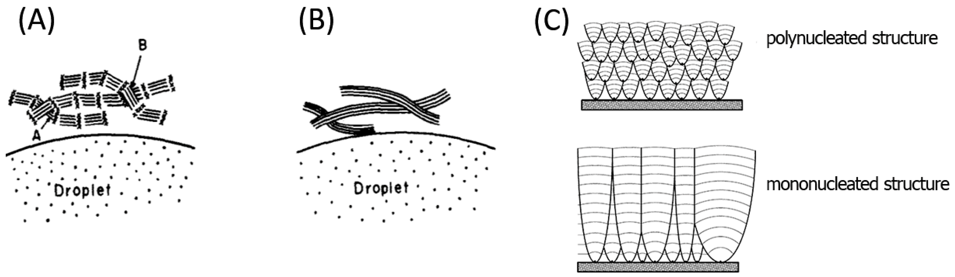
Pyrolytic Graphite is a perfect artificial graphite produced by annealing of Pyrolytic Carbon—unordered graphite material that is obtained by thermal cracking of carbon containing gas, mainly methane, on a hot surface (Figure 1) [11]. The material has a two-dimensional ordering of crystal cells, a clear conical structure and mosaic spread of 30°.
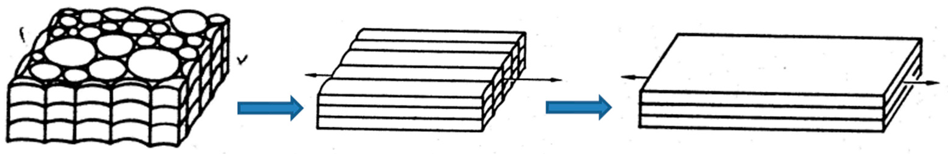
Annealing at temperatures near 3000 °C orders the material structure (Figure 2). The structural changes are enhanced when annealing is accompanied by deformation. Different combinations of the annealing temperature and the deformation type lead to different structure and different forms of PG [13]. The forms with well-aligned structure are considered as graphite mosaic crystal and used as optical element for X-rays and neutrons.
Pyrolytic graphite could be considered to some approximation as a set of bulk graphene chips and has very interesting properties: it is pure carbon (99.999%) with highly anisotropic structure and properties. Its thermal conductivity in C-C plane is about 2000 W/(m·K) that is four times higher than for Cu. The material is electrically conductive along the C-C plane and is an insulator in the perpendicular direction. It can withstand high thermal and radiation loads, is chemically neutral and ecologically friendly [14].
The PG properties result in the largest integrated reflectivity of graphite among all other crystals. The dramatic increase of the integral reflectivity in comparison to ideal crystals is governed by crystal mosaicity that determines the width of the reflected energy window. Low absorption leads to the increase of the reflecting layer thickness and of the number of crystal planes involved in X-ray diffraction. As the result, the integral reflectivity of GrO is more than an order of magnitude higher than for ideal crystals [15,16]. The crystal brightness is enhanced by efficient focusing. The optics had high collection efficiency due to the possibility of being realized in any shape including full figure of revolution [5] and short focus geometries [6]. When the crystal is placed equidistant between source and detector, mosaic focusing in the detection plane provides not only additional reflectivity increase, but also high resolving power [17].
GrO works in a large energy range, including the energies higher than 10 keV [18,19]. Due to its unique brightness, the higher orders of reflection (d004, d006) could be used for widening the working energy range and increasing the crystal resolution. GrO is very robust: it endures increased temperatures, radiation and unfriendly handling.
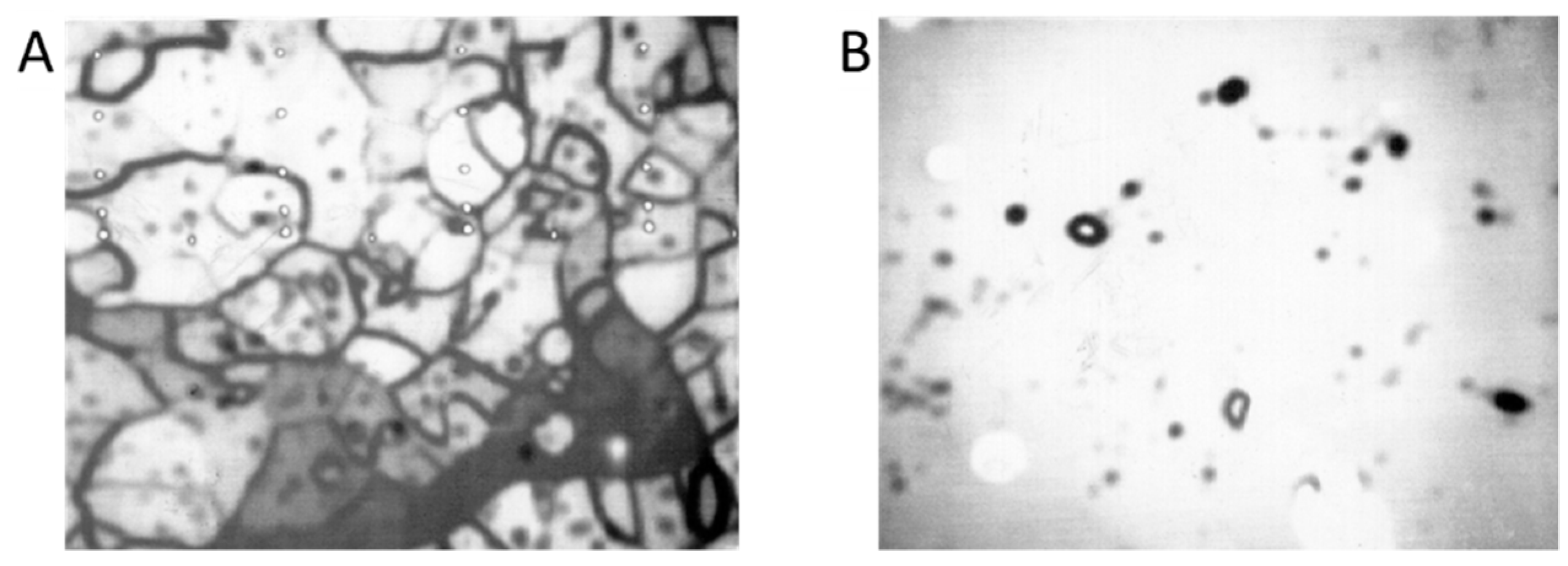
The PG layer has a complex anisotropic structure. It contains big structural units—blocks or domains consisting of smaller crystallites [20]. The size of the blocks (domains) is a few hundreds µm along the surface and an order of magnitude less in the perpendicular direction (Figure 3) [21]. The average size of the structural units depends on the annealing procedure. The wide scatter of the results is clearly seen in review [22] where the average size of blocks and crystallites in conventional HOPG measured by different methods and different researchers were collected. We guessed that the difference in values is derived mainly from unequal annealing conditions of the samples obtained from different sources and by different procedures.
Some researchers noted the existence of reflecting areas of ≤1 mm size in HAPG [23,24]. It is still not clear where these areas are blocks of increased size or there is one more structural level.
The units are well aligned along the average direction of C-C planes. The mosaicity that could be considered as a deviation of the structural unit orientation from this average plane is mainly determined by blocks; the crystallites within the block are misaligned at an angle of about 0.1°.
The variation of annealing procedure changes the material structure that in its turn determines the mosaic spread and flexibility of the material. Currently, Optigraph uses three forms of PG for optical applications, which differ by annealing history and as the result by crystal structure and characteristics they supply to the corresponding GrO.
2.1. Types of GrO
2.1.1. Optics Based on Conventional HOPG Crystal
HOPG as a monochromator and model object for fundamental research was developed in the beginning of 70 s [14]. As an optical element, HOPG was famous for its unusual brightness; however, it has moderate resolution owing to relatively big mosaic spread. Commercially available crystals have mosaic spread of 0.4° ± 0.1° or bigger. The bending of HOPG occurs at 3000 °C during annealing under pressure on concave/convex graphite pistons.
From the very beginning, there were attempts to design graphite optics on the base of flat and singly bent graphite monochromators [25]. Similarly to ideal crystals, the thin plates of HOPG were slightly bent and glued on a substrate; however the devices did not have significant efficiency in spite of the highest brightness of graphite monochromator. Until recently, this optics has some niche application for simple instruments where a moderate performance is compensated by relatively low cost.
The impossibility of the crystal bending to small radii, difficulties in production of custom and doubly bent shapes prevented appearing efficient GrO on the market.
2.1.2. HOPG Optics
The extensive research of the factors determining the PG structure and properties made at the end of last century [14,20,26,27] resulted in a novel approach to GrO that was designed on the base of thin flexible films [28].
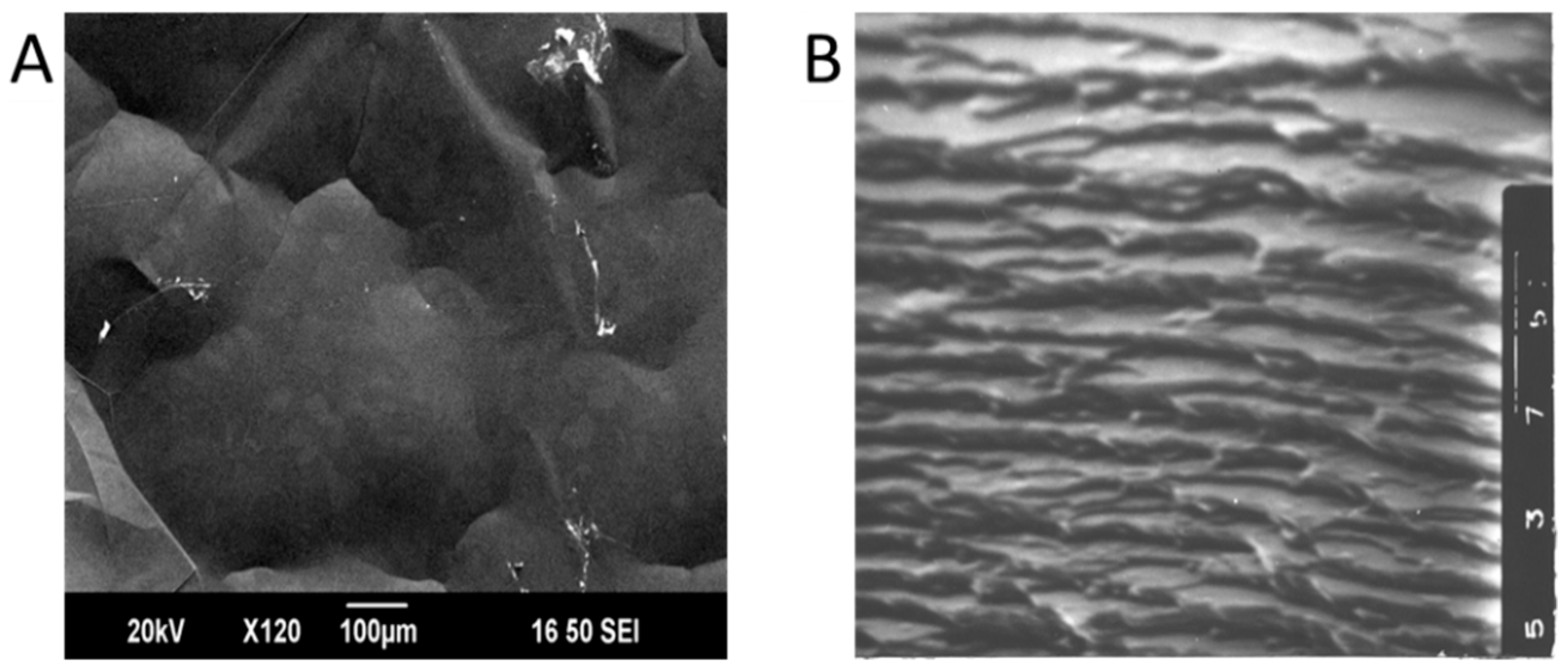
The film flexibility is a result of a special combination of annealing and deformation that eliminate the vast defect regions along the grain boundaries existing in conventional HOPG. Figure 4 shows the grain structure of conventional and flexible HOPG of the same mosaicity by acoustic microscopy [28]. In conventional HOPG, the grain boundaries are marked by contrast zones that are not visible in the flexible form.
The film flexibility grants a chance to produce custom shaped optics at room temperature and notably decreases the production costs. Moreover, the structural changes allow attaining significantly lower crystal mosaicity than by classical technology.
It is of a special importance that the resolution of bent optics does not degrade versus a flat one. The flexible films are bent plastically at room temperature, and the deformation causes neither stress, nor crucial structural changes [29].
HOPG optics is made of a set of thin films with a mosaicity of 0.1 degree. The thickness of a film could be from 5 to 20 µm. The films are split off from the material denoted as flexible HOPG. The films adhere to each other and to optically polished substrate without glue and a layer of required thickness could be deposited on a substrate of any shape at room temperature. The mosaicity of the optics increases with the number of the films involved.
HOPG optics could be produced with radii down to a few mm and as full figure of revolution. The optics offers efficient focusing with moderate resolution and relatively wide bandpass.
HOPG optics finds application mainly in the fields where the priority is the flux and not the resolution. The optics has relatively moderate requirements to the substrate and is preferable for complex short focus shapes [30,31].
Providing efficient focusing, HOPG-optics still retains moderate mosaic spread similar to the conventional HOPG. In spite of a low mosaic spread of very thin films the optics with practically useful thickness of reflecting layer does not fit the high-resolution applications.
2.1.3. HAPG Optics
The upgrade of the annealing procedure permitted to increase by an order of magnitude the thickness of flexible monofilms with mosaicity of about 0.1°. The film adheres to optically polished substrate and has increased flexibility. As the annealing procedure significantly differs from the technology of conventional and flexible HOPG, the material got a special name HAPG.
HAPG has more perfect structure and decreased intrinsic width in comparison with both variants of HOPG. That leads to better combination of sensitivity and resolution. In von Hamos geometry the HAPG optics reaches a resolution close to ideal crystals keeping an order of magnitude higher brightness [29,32]. The direct comparison of HAPG optics at von Hamos geometry with ideal crystals such as Si [16], Ge [15] and with mosaic crystals such as LiF [16,23] demonstrates in all cases a significant integrated reflectivity gain at comparable resolving power.
Tuning the GrO to a given task one could not only choose the required form of PG layer and the optics geometry, but also vary the parameters of reflecting layer in order to achieve maximal efficiency.
The resolution and brightness of the optics both depend on the thickness and mosaicity of graphite layer; however, the trends are contrariwise. X-rays penetrate relatively deep into the graphite and reflect from the depth up to a few hundred microns depending on the energy and crystal mosaicity. Aberrations derived from the mismatch between the rays reflected from the top and the bottom of the reflecting layer limit the crystal thickness by the resolution on request. A smaller curvature radius needs a thinner crystal layer if the same resolution should be achieved.
Besides the depth broadening, there are other factors degrading the GrO energy resolution; they are thoroughly discussed in [33,34]. Increased collection solid angle does not always result in increased efficiency, because a considerable fraction of the collected photons could be lost due to aberrations; thus, the crystal with decreased mosaicity could compensate its potentially lower reflectivity by tight focusing. As a result, the optimal type of GrO, as well as the choice between ideal crystals and graphite optics, depends on the required spectral resolution and other limitations of the given application [35].
To choose the thickness of the graphite layer for the optimal ratio between resolution and brightness of the optics one needs not only theoretical estimations, but also experimental data that establish the correlation between mosaicity, reflectivity and thickness of the layer for different PG forms and deposition procedures.
The graphite film follows the substrate precisely; thus, the substrate availability determines the chance to realize optics according to the theoretical calculation. The films adhere to the optically polished substrate made from glass, quartz and some other materials. Aluminum substrates often require some gluing. However, aluminum substrates could offer more various shapes, could work under trying conditions and they are cheaper and easier to handle. Therefore, the choice of substrate material also becomes a question of compromise and experiments revealing the influence of the substrate on the optics parameters are essential.
In order to clarify these questions, we analyzed characteristics such as mosaic spread and integrated reflectivity of the graphite layers deposited on different substrates, in different ways and of different thickness.
3. Results
3.1. HAPG versus HOPG
The thickness of a single film with mosaicity of 0.1° is limited by 10–15 µm for flexible HOPG and 120 µm for HAPG. HOPG films up to 50 µm thick could still adhere to optically polished glass substrate; however, the mosaicity of such films increases up to 0.25° and the flexibility significantly decreases. Increased surface roughness of the substrate results in worse film adhesion. For the aluminum substrates used in this work, the maximal thickness of the adhering film decreased down to 30/80 µm for HOPG and HAPG films, respectively.
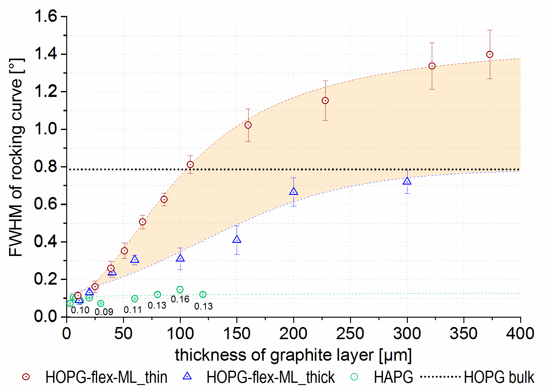
As films adhere not only to optically polished substrate, but also to each other, there is a possibility to increase the thickness of reflecting layer using a set of films. The approach results in a significant mosaicity increase with the number of the films involved. The required thickness could be obtained by the deposition of a few thicker films with increased mosaicity or a bigger amount of thin films with mosaicity of 0.1°. To compare both ways of deposition, the mosaicity and reflectivity of HOPG layers produced from thin films (5–10 µm each) and from films of maximal possible thickness (30–50 µm each) were measured (Figure 5).
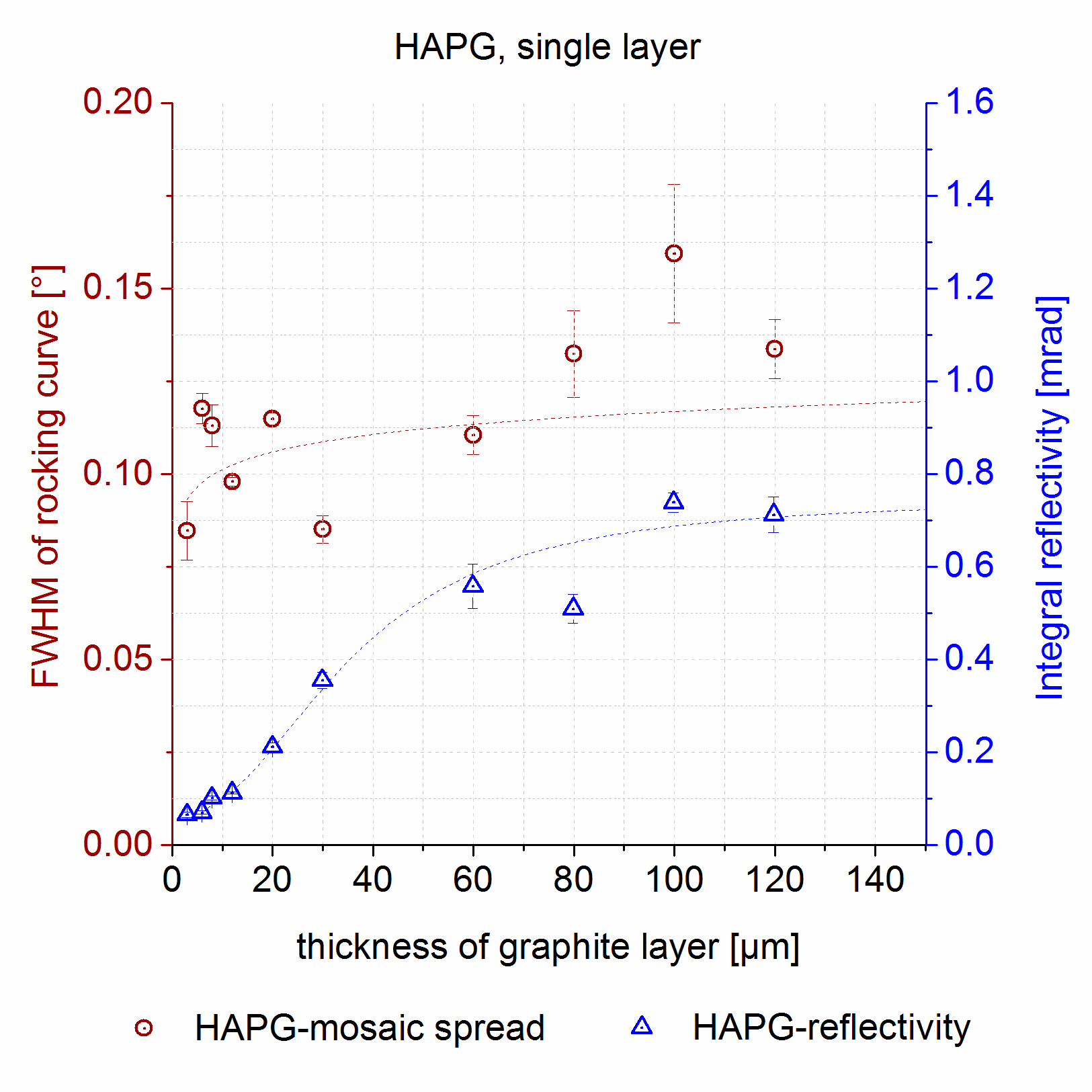
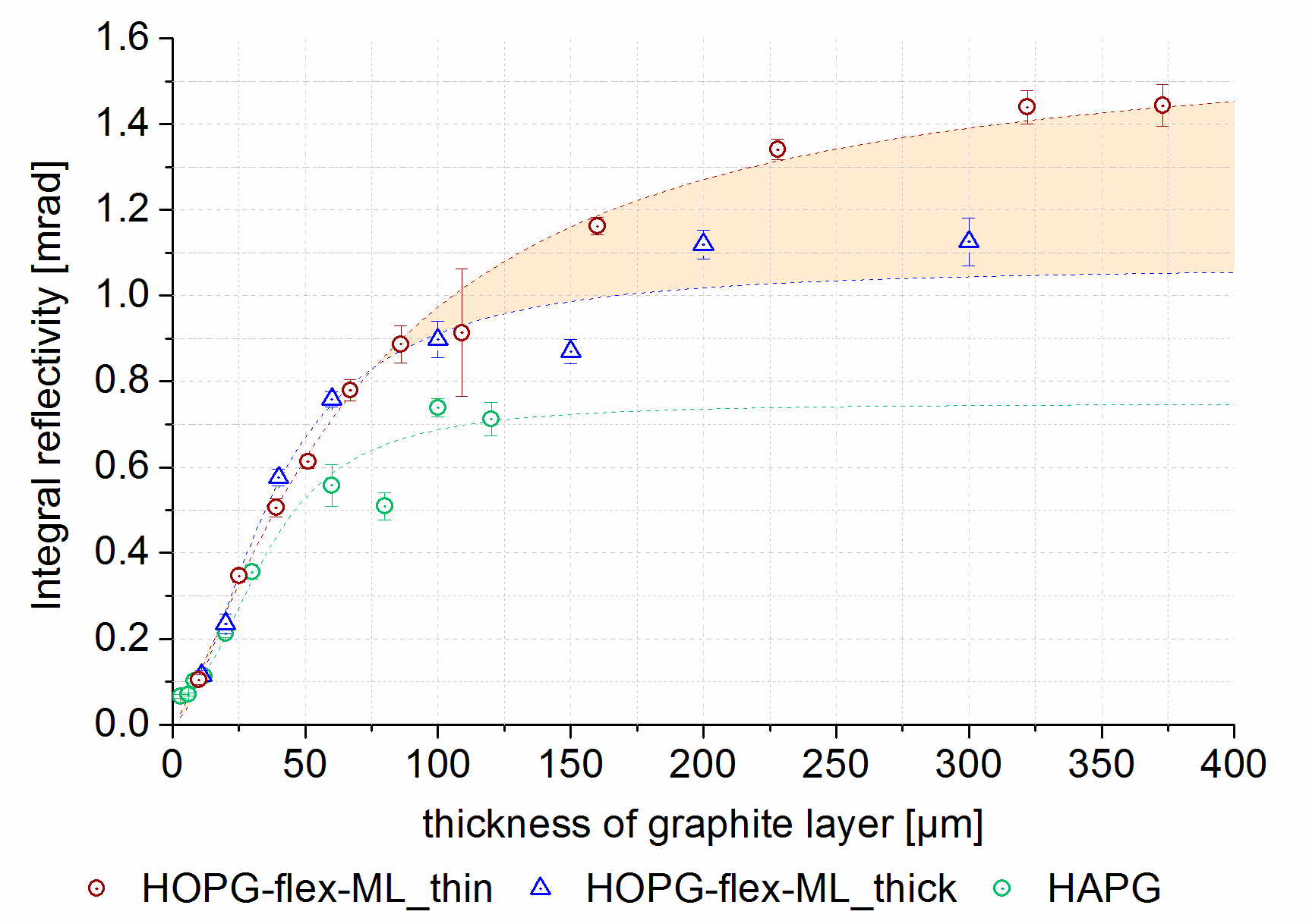
In the “thin-film method” the film mismatch rapidly increases the mosaicity of HOPG optics up to the values higher than those of the source material—flexible HOPG (up to 1.5° in comparison to 0.8°). In the case of “thick-film method”, the mosaicity increases slower and reaches the values of the source material. The HAPG layer could be applied as a single film up to 120 µm thick retaining the mosaicity of about 0.1° (Figure 6). Stacking of HAPG layers from a set of single films also leads to mosaicity similar, but slower, increase to flexible HOPG. For example, the mosaicity of 40 µm HAPG layer made of 10 films exceeded only twice the mosaicity of the monofilm variant. For convenient comparison of HOPG and HAPG the results for HAPG are also additional placed on Figure 5 and Figure 7. The reflectivity of the HOPG layer reaches a “plateau” at 200–300 µm (Figure 7) and this thickness of the reflecting layer is typically used for HOPG optics working below 10 keV. The mosaicity of such optics lies in the range of 0.8°–1.5° (Figure 5). Due to lower mosaicity, HAPG optics has a smaller integral reflectivity versus HOPG optics, while the peak reflectivity is the same.
3.2. Glass Substrates versus Aluminum Substrates
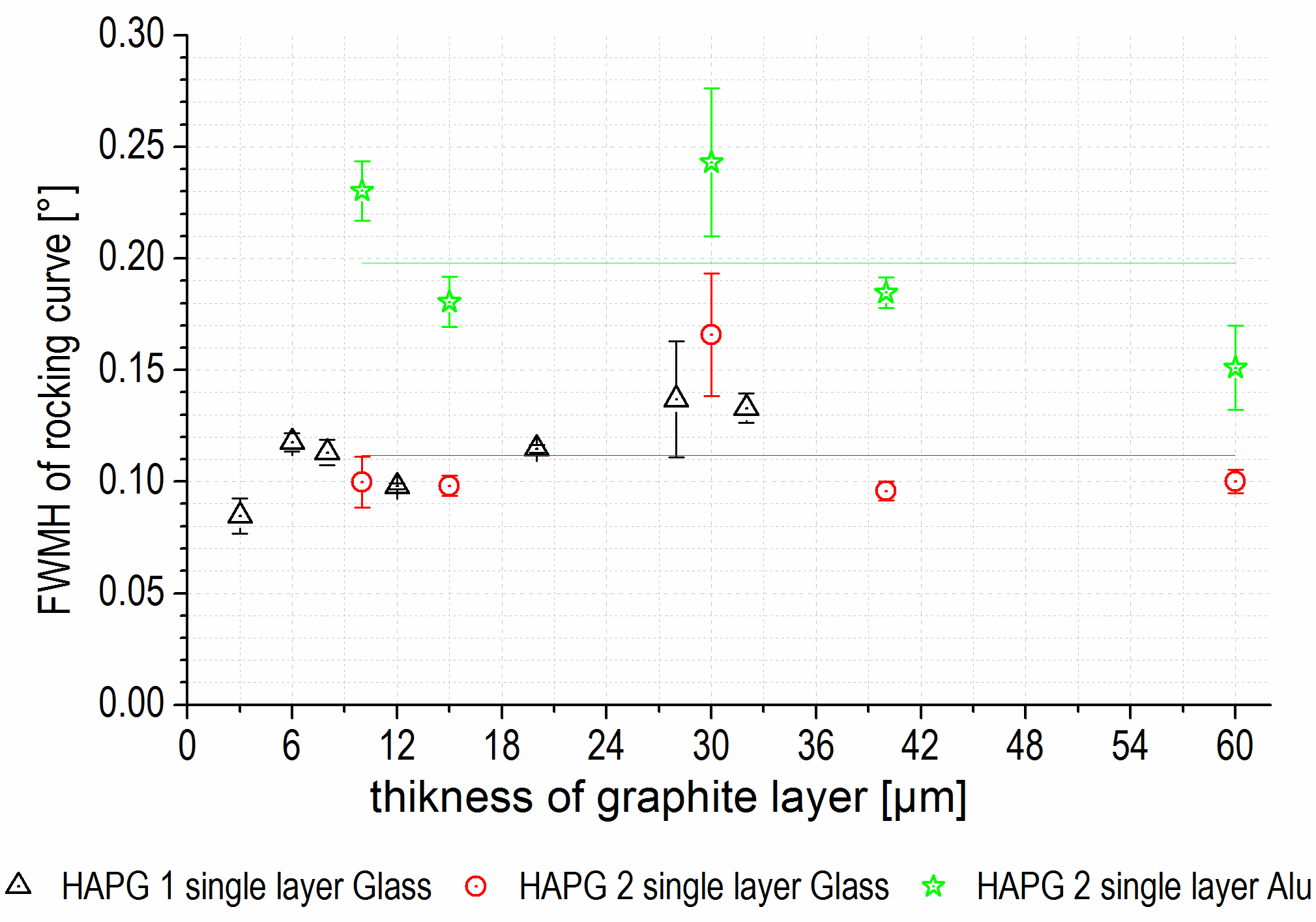
In order to test the influence of the substrate materials on the characteristics of GrO, aluminum and glass were used as substrates for HAPG films of different thickness. A single film layer was deposited sequentially on two types of the substrates. Each film was deposited first on aluminum substrate of worse surface quality and afterwards it was redeposited on optically polished glass substrate. The mosaicity was measured after first and second deposition. The same HAPG film on well-polished aluminum substrate has twice higher mosaicity than on optically polished glass (Figure 8). We would like to emphasize that the film improved its mosaicity being transferred on a substrate of better surface quality from a worse substrate.
Mosaic spread of the redeposited films was similar to the mosaicity of the films directly stacked on glass (red circles and red triangles in Figure 8). It demonstrated how robust and reliable the graphite films were. Due to enhanced flexibility, the film follows the substrate roughness and that made the optics characteristics very sensitive to the substrate quality.
A good illustration of high stability of the deposition method is the results for 30 µm thick sample given at Figure 8. The film has anomalous high mosaicity in comparison to other films of the series obviously due to a local structural defect. The deviation of drop down value was similar on both substrates. It looks like the redeposition just aligns the structural units of the film along the substrate surface. The film replicated the surface roughness without any structural changes within the film.
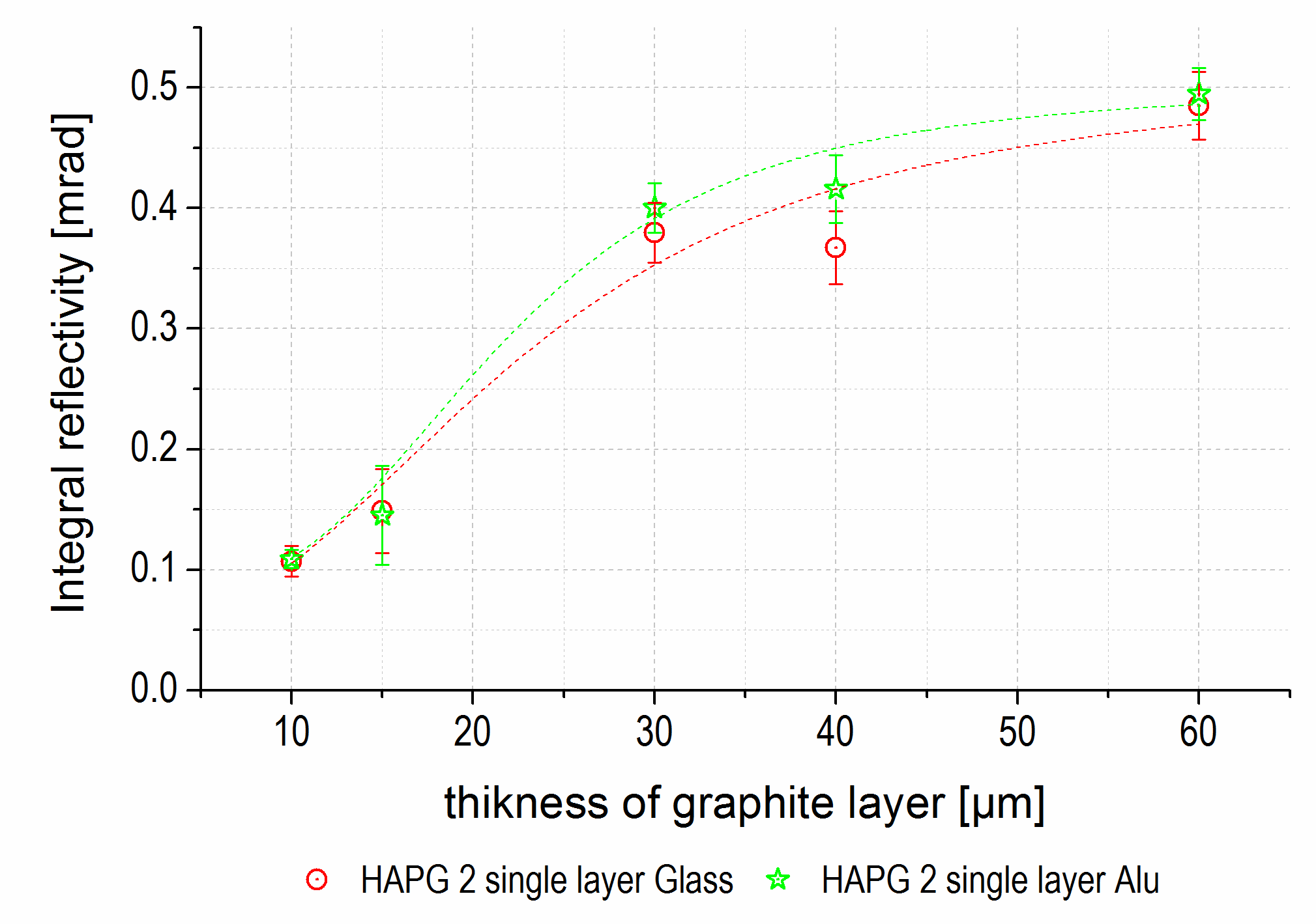
Contrary to mosaic spread, the integral reflectivity does not show significant dependence on substrate material (Figure 9).
4. Materials and Methods
The measurements were fulfilled by the diffractometer D8 ADVANCE ECO from Bruker (Bruker AXS GmbH, Karlsruhe, Germany) in Bragg-Brentano configuration. As X-ray source, a tube with copper anode with 40 keV and 25 µA was used. Göbel-mirror and 2-bounce monochromator formed a parallel beam with about 1 mm × 9 mm spot in the sample plane. Measurements of the rocking curve of GrO were performed in reflection order 002 with the Cu Ka emission of the Cu anode within Θ = 13.29° ± 2° by the SSD160 camera. To calculate the integral reflectivity, the intensity of incident X-ray beam was directly measured by 2-theta scan around 0° with SSD160.
The thin films of HOPG/HAPG with different thickness were prepared by splitting off from the same batches of bulk materials (Optigraph, Berlin, Germany). As substrates optically polished BK7-glass plates from Thorlabs GmbH Dachau/Munich, Bavatia, Germany and aluminum plates from Kugler, Germany with surface roughness Ra = 5 nm (specified by producer) were used. Different alloys of aluminum were tested and the one (Rapidly Solidified Aluminum-6061) with the best adhesion to graphite films was used for further experiments. For direct measurement of the rocking curve, all substrates were flat.
Each measurement value depicted on the figures represents an average of single measurements of Full Width at Half Maximum (FWHM) of rocking curve made at 10 different points along the sample. In the experiment comparing the different forms of PG on glass substrate, these points were fixed relative to the substrate and not to the position on the varying graphite layers. In the experiment with glass and aluminum substrates, the points were fixed relative to their position on graphite layer, which was deposited on both substrates subsequently.
5. Conclusions
Optimization of the Graphite Optics to a given task and set-up includes not only the choice of PG and the estimation of the optics shape, but also the optimization of deposition process in order to get the combination of thickness and mosaicity of the reflecting layer required for maximizing the optics efficiency.
The correlation between the mosaicity and the thickness in HOPG optics restricts the set of existing combinations. The number of combinations could be increased by producing HAPG optics in the way similar to HOPG optics as a set of monofilms. The increase of the mosaicity fills the gap between the two types of the optics. As a result, almost any combination of thickness and mosaicity could be fulfilled and any optics according to theoretical estimation could be realized.
The quality of the substrate surface could be a crucial parameter that influences the optics performance. Therefore, the availability of the substrate of required shape and surface quality usually determines the possibility to manufacture the optics according to the requirements.
Graphite Optics is a powerful and versatile device for a wide set of applications. Due to its high variability, it could find a place in many new branches of advanced science and technology and could encourage the researchers to realize their current and future ideas.
Author Contributions
Conceptualization, project administration, funding acquisition, resources: I.G. and A.A.; methodology, data curation, investigation, validation, formal analysis, visualization: G.G.; writing—original draft preparation, writing—review and editing: I.G., A.A. and G.G.
Funding
This research received no external funding.
Conflicts of Interest
The authors declare no conflict of interest.
References
- Malzer, W.; Grötzsch, D.; Gnewkow, R.; Schlesiger, C.; Kowalewski, F.; Van Kuiken, B.; DeBeer, S.; Kanngießer, B. A laboratory spectrometer for high throughput X-ray emission spectroscopy in catalysis research. Rev. Sci. Instrum. 2018, 89, 113111. [Google Scholar] [CrossRef]
- Scordo, A.; Curceanu, C.; Miliucci, M.; Shi, H.; Sirghi, F.; Zmeskal, J. VOXES: A high precision X-ray spectrometer for diffused sources with HAPG crystals in the 2–20 keV range. J. Inst. 2018, 13, C04002. [Google Scholar] [CrossRef]
- Kolmogorov, Y.; Trounova, V. Analytical potential of EDXRF using toroidal focusing systems of highly oriented pyrolytic graphite (HOPG). X-Ray Spectrom. 2002, 31, 432–436. [Google Scholar] [CrossRef] [Green Version]
- Chevallier, P.; Brissaud, I.; Wang, J.X. Quantitative analysis by synchrotron radiation induced X-ray fluorescence at lure. Nuclear Instrum. Methods Phys. Res. Sect. B Beam Interact. Mater. Atoms 1990, 49, 551–554. [Google Scholar] [CrossRef]
- Pease, D.M.; Daniel, M.; Budnick, J.I.; Rhodes, T.; Hammes, M.; Potrepka, D.M.; Sills, K.; Nelson, C.; Heald, S.M.; Brewe, D.I.; et al. Log spiral of revolution highly oriented pyrolytic graphite monochromator for fluorescence x-ray absorption edge fine structure. Rev. Sci. Instrum. 2000, 71, 3267–3273. [Google Scholar] [CrossRef]
- Heckel, J.; Wissmann, D. Optimization of ED-XRF Excitation Configuration Parameters to Determine Trace-Element Concentrations in Organic and Inorganic Sample Matrices. Spectroscopy 2016, 31, 24–29. [Google Scholar]
- Schlesiger, C.; Anklamm, L.; Stiel, H.; Malzer, W.; Kanngießer, B. XAFS spectroscopy by an X-ray tube based spectrometer using a novel type of HOPG mosaic crystal and optimized image processing. J. Anal. Atom. Spectrom. 2015, 30, 1080–1085. [Google Scholar] [CrossRef] [Green Version]
- SIGRAY QuantumLeap-XAS, X-ray Absorption Spectroscopy System. Available online: https://www.qd-uki.co.uk/admin/images/uploaded_images/%5BQuantumLeap_Brochure%5D20180913_QuantumLeap_Brochure-cmp.pdf (accessed on 9 January 2019).
- Döppner, T.; Kritcher, A.L.; Neumayer, P.; Kraus, D.; Bachmann, B.; Burns, S.; Falcone, R.W.; Glenzer, S.H.; Hawreliak, J.; House, A.; et al. Qualification of a high-efficiency, gated spectrometer for X-ray Thomson scattering on the National Ignition Facility. Rev. Sci. Instrum. 2014, 85, 11D617. [Google Scholar] [CrossRef]
- Optigraph: HOPG, Highly Oriented Pyrolytic Graphite, Graphite Monochromator, Doubly Bent Graphite Monochromator. Available online: http://www.optigraph.eu/ (accessed on 26 November 2018).
- Je, J.H.; Lee, J.-Y. How is pyrolytic carbon formed? Transmission electron micrographs which can explain the change of its density with deposition temperature. Carbon 1984, 22, 317–319. [Google Scholar] [CrossRef]
- Tombrel, F.; Rappeneau, F. Préparation et Structure des Pyrocarbones. In Les Carbones; Collection de Chimie Physique; Mason et Cie.: Paris, France, 1965; pp. 783–836. (In French) [Google Scholar]
- Jenkins, G.M. Basal plane distortion in pyrolytic carbon. Carbon 1969, 7, 9–14. [Google Scholar] [CrossRef]
- Moore, A.W. Highly oriented pyrolitic graphite. In Chemistry and Physics of Carbon; Dekker: New York, NY, USA, 1973; Volume 11, pp. 69–185. ISBN 978-0-8247-6051-9. [Google Scholar]
- Legall, H.; Stiel, H.; Arkadiev, V.; Bjeoumikhov, A.A. High spectral resolution x-ray optics with highly oriented pyrolytic graphite. Opt. Express 2006, 14, 4570–4576. [Google Scholar] [CrossRef] [PubMed]
- Haschke, M. Laboratory Micro-X-Ray Fluorescence Spectroscopy: Instrumentation and Applications; Springer Series in Surface Sciences; Springer International Publishing: Heidelberg, Germany, 2014; Volume 55, ISBN 978-3-319-04863-5. [Google Scholar]
- Yaakobi, B.; Burek, A. Crystal diffraction systems for X-ray spectroscopy, imaging, and interferometry of laser fusion targets. IEEE J. Quantum Electron. 1983, 19, 1841–1854. [Google Scholar] [CrossRef]
- Hoheisel, M.; Lawaczeck, R.; Pietsch, H.; Arkadiev, V. Advantages of monochromatic x-rays for imaging. In Proceedings of the Medical Imaging 2005: Physics of Medical Imaging; International Society for Optics and Photonics: San Diego, CA, USA, 2005; Volume 5745, pp. 1087–1096. [Google Scholar]
- Jost, G.; Golfier, S.; Lawaczeck, R.; Weinmann, H.-J.; Gerlach, M.; Cibik, L.; Krumrey, M.; Fratzscher, D.; Rabe, J.; Arkadiev, V.; et al. Imaging-therapy computed tomography with quasi-monochromatic X-rays. Eur. J. Radiol. 2008, 68, S63–S68. [Google Scholar] [CrossRef] [PubMed]
- Tuffanelli, A.; del Rio, M.S.; Pareschi, G.; Gambaccini, M.; Taibi, A.; Fantini, A.; Ohler, M. Comparative characterization of highly oriented pyrolytic graphite by means of diffraction topography. In Proceedings of the SPIE’s International Symposium on Optical Science, Engineering, and Instrumentation, Denver, CO, USA, 18–23 July 1999; pp. 192–199. [Google Scholar]
- Antonov, A.; Arkadiev, V.; Beckhoff, B.; Erko, A.; Grigorieva, I.; Kanngießer, B.; Vidal, B. 3.4 Optics for Monochromators. In Handbook of Practical X-ray Fluorescence Analysis; Springer: Berlin, Germany; New York, NY, USA, 2006; pp. 142–198. ISBN 978-3-540-28603-5. [Google Scholar]
- Katrakova, D. Anwendungen der Orientierungsabbildenden Mikroskopie zur Gefügecharakterisierung kristalliner Werkstoffe. Ph.D. Thesis, Universität des Saarlands, Saarbrücken, Germany, 2002. (In German). [Google Scholar]
- Zastrau, U.; Woldegeorgis, A.; Förster, E.; Loetzsch, R.; Marschner, H.; Uschmann, I. Characterization of strongly-bent HAPG crystals for von-Hámos x-ray spectrographs. J. Instrum. 2013, 8, P10006. [Google Scholar] [CrossRef]
- Gerlach, M.; Anklamm, L.; Antonov, A.; Grigorieva, I.; Holfelder, I.; Kanngießer, B.; Legall, H.; Malzer, W.; Schlesiger, C.; Beckhoff, B. Characterization of HAPG mosaic crystals using synchrotron radiation. J. Appl. Crystallogr. 2015, 48, 1381–1390. [Google Scholar] [CrossRef]
- Boslett, J.A.; Towns, R.L.R.; Megargle, R.G.; Pearson, K.H.; Furnas, T.C. Determination of parts per billion levels of electrodeposited metals by energy dispersive x-ray fluorescence spectrometry. Anal. Chem. 1977, 49, 1734–1737. [Google Scholar] [CrossRef]
- Dresselhaus, M.S.; Dresselhaus, G. Intercalation compounds of graphite. Adv. Phys. 2002, 51, 1–186. [Google Scholar] [CrossRef] [Green Version]
- Freund, A.K. Mosaic crystal monochromators for synchrotron radiation instrumentation. Nuclear Instrum. Methods Phys. Res. Sect. A Accel. Spectrom. Detect.Assoc. Equip. 1988, 266, 461–466. [Google Scholar] [CrossRef]
- Grigorieva, I.G.; Antonov, A.A. HOPG as powerful x-ray optics. X-Ray Spectrom. 2003, 32, 64–68. [Google Scholar] [CrossRef]
- Legall, H.; Stiel, H.; Antonov, A.; Grigorieva, I.; Arkadiev, V.; Bjeoumikhov, A.; Erko, A. A New Generation of X-Ray Optics Based on Pyrolytic Graphite. In Proceedings of the FEL 2006, Berlin, Germany, 27 August–1 September 2006; pp. 798–801. [Google Scholar]
- HORIBA MESA-7220, X-ray Fluorescence Sulfur and Chlorine. Available online: http://www.horiba.com/us/en/scientific/products/sulfur-in-oil/mesa-7220-details/mesa-7220-x-ray-fluorescence-sulfur-and-chlorine-12793/ (accessed on 16 November 2018).
- SPECTRO XEPOS RFA-Spektrometer—EDRFA. Available online: www.spectro.de/produkte/rfa-spektrometer/xepos-spektrometer-edrfa (accessed on 19 November 2018).
- Anklamm, L.; Schlesiger, C.; Malzer, W.; Grötzsch, D.; Neitzel, M.; Kanngießer, B. A novel von Hamos spectrometer for efficient X-ray emission spectroscopy in the laboratory. Rev. Sci. Instrum. 2014, 85, 053110. [Google Scholar] [CrossRef]
- Ice, G.E.; Sparks, C.J. Mosaic crystal X-ray spectrometer to resolve inelastic background from anomalous scattering experiments. Nuclear Instrum. Methods Phys. Res. Sect. A Accel. Spectrom. Detect. Assoc. Equip. 1990, 291, 110–116. [Google Scholar] [CrossRef]
- Zastrau, U.; Brown, C.R.D.; Döppner, T.; Glenzer, S.H.; Gregori, G.; Lee, H.J.; Marschner, H.; Toleikis, S.; Wehrhan, O.; Förster, E. Focal aberrations of large-aperture HOPG von-Hàmos x-ray spectrometers. J. Instrum. 2012, 7, P09015. [Google Scholar] [CrossRef]
- Ao, T.; Harding, E.C.; Bailey, J.E.; Loisel, G.; Patel, S.; Sinars, D.B.; Mix, L.P.; Wenger, D.F. Relative x-ray collection efficiency, spatial resolution, and spectral resolution of spherically-bent quartz, mica, germanium, and pyrolytic graphite crystals. J. Quant. Spectrosc. Radiat. Transf. 2014, 144, 92–107. [Google Scholar] [CrossRef]
Figure 1.
Production of Pyrolytic Carbon—initial material for Pyrolytic Graphite. (A) Before dehydrogenation; (B) after dehydrogenation (Reproduced with permission from [11] © Elsevier); (C) cone structure of pyrolytic carbon [12], modified.

Figure 2.
Schematic representation of structural changes associated with annealing under pressure (Reproduced with permission from [13] © Elsevier, modified).
Figure 2.
Schematic representation of structural changes associated with annealing under pressure (Reproduced with permission from [13] © Elsevier, modified).

Figure 3.
Structure of Pyrolytic Graphite (PG)-layers in Graphite Optics (GrO) by Scanning Electron Microscope. (A) Two level structure in plane: big blocks of a few hundreds µm, small crystallites of 10–30 µm; (B) the structure of crystal edge after laser cut: the edges of the blocks of 1–3 µm thick are clearly seen. (Reproduced with permission from [21] © Springer, modified).

Figure 4.
Structure of rigid and flexible HOPG films by acoustic microscope. (A) Rigid material, could be bent plastically at 3000 °C or elastically as a film of 50–200 µm; (B) flexible HOPG is acoustically transparent. (Reproduced with permission from [28]. © Wiley-VCH Verlag GmbH & Co. KGaA).
Figure 4.
Structure of rigid and flexible HOPG films by acoustic microscope. (A) Rigid material, could be bent plastically at 3000 °C or elastically as a film of 50–200 µm; (B) flexible HOPG is acoustically transparent. (Reproduced with permission from [28]. © Wiley-VCH Verlag GmbH & Co. KGaA).

Figure 5.
Mosaic spread of GrO on glass substrate depending on graphite layer thickness: red circles—HOPG layer composed of thin films (5–10 µm); blue triangles—HOPG layer composed of thick films (30–50 µm); green circles—HAPG layer applied as a single film. The error bars represent the standard deviations of every 10 measurement points.

Figure 6.
Mosaicity and reflectivity of HAPG deposited as a single film on glass substrate depending on the graphite layer thickness: red circles—mosaicity; blue triangles—reflectivity. The error bars represent the standard deviations of every 10 measurement points.
Figure 6.
Mosaicity and reflectivity of HAPG deposited as a single film on glass substrate depending on the graphite layer thickness: red circles—mosaicity; blue triangles—reflectivity. The error bars represent the standard deviations of every 10 measurement points.

Figure 7.
Reflectivity of GrO on glass substrate depending on graphite layer thickness: red circle—HOPG layer composed of thin films (5–10 µm); blue triangles—HOPG layer composed of thick films (30–50 µm); green circles—HAPG layer applied as a single film. The error bars represent the standard deviations of every 10 measurement points.

Figure 8.
Mosaic spread of GrO on different substrates depending on graphite layer thickness: green stars—HAPG layer applied on aluminum; red circles—HAPG layer applied on glass (the same layer and the same measurement points as by the green stars); black triangles—HAPG layer directly applied on glass. The error bars represent the standard deviations of every 10 measurement points.

Figure 9.
Integral reflectivity of GrO on different substrates depending on graphite layer thickness: green stars—HAPG layer applied on aluminum; red circles—HAPG layer applied on glass (the same layer and the same measurement points as by the green stars).
Figure 9.
Integral reflectivity of GrO on different substrates depending on graphite layer thickness: green stars—HAPG layer applied on aluminum; red circles—HAPG layer applied on glass (the same layer and the same measurement points as by the green stars).

© 2019 by the authors. Licensee MDPI, Basel, Switzerland. This article is an open access article distributed under the terms and conditions of the Creative Commons Attribution (CC BY) license (http://creativecommons.org/licenses/by/4.0/).
Share and Cite
MDPI and ACS Style
Grigorieva, I.; Antonov, A.; Gudi, G. Graphite Optics—Current Opportunities, Properties and Limits. Condens. Matter 2019, 4, 18. https://doi.org/10.3390/condmat4010018
AMA Style
Grigorieva I, Antonov A, Gudi G. Graphite Optics—Current Opportunities, Properties and Limits. Condensed Matter. 2019; 4(1):18. https://doi.org/10.3390/condmat4010018
Chicago/Turabian StyleGrigorieva, Inna, Alexander Antonov, and Gennadi Gudi. 2019. "Graphite Optics—Current Opportunities, Properties and Limits" Condensed Matter 4, no. 1: 18. https://doi.org/10.3390/condmat4010018