Hybrid Carbon Nano-Fibers with Improved Oxidation Resistance


Department of Chemical and Materials Engineering, University of Dayton, 300 College Park, Dayton, OH 45469, USA
*
Author to whom correspondence should be addressed.
Ceramics 2019, 2(1), 25-33; https://doi.org/10.3390/ceramics2010003
Submission received: 1 December 2018
/
Revised: 29 December 2018
/
Accepted: 6 January 2019
/
Published: 10 January 2019
Abstract
:Hybrid Carbon-Silicon Carbide (C-SiC) nano-fibers were fabricated while using a mixture of polyacrylonitrile (PAN) and silicon (Si) nanoparticles as precursors. The microstructure of the material was examined using X-ray diffraction and Raman spectroscopy as a function of processing temperature and holding time. A complete transformation of Si to SiC occurred at 1250 °C. However, for heat treatments below 1000 °C, three distinct phases, including Si, C, and SiC were present. The effect of microstructural changes, due to the heat treatment, on oxidation resistance was determined using thermogravimetric analysis (TGA). Furthermore, the char yield showed exponential growth with increasing the carbonization temperature from 850 °C to 1250 °C. The holding times at higher temperatures showed a significant increase in thermal properties because of SiC grain growth. At longer holding times, the SiC phase has the function of bothcoating and reinforcing phase. Such structural changes were related to fibers mechanical properties. The tensile strength was the highest for fiber carbonized fibers at 850 °C, while the modulus increased monotonically with increasing carbonization temperature.
1. Introduction
Carbon fibers (CFs) are fibers consisting of about 90% carbon elements with high strength (3–7 GPa) and modulus (200–500 GPa) [1,2,3,4]. They display good thermo-chemical stability in nonoxidative environments. CFs can have good thermal and electrical conductivities, and excellent creep resistance [5,6]. They have been utilized in many applications, such as aerospace [7], highway transportation [8], military [9], turbine blades [10], construction [11], energy conversion and storage [12], and self-sensing devices [13]. CFs can be fabricated using polymeric precursors, such as acrylic, cellulosic, pitch, and polyacrylonitrile (PAN) precursors [2,14,15] by subsequent heat treatment.
The mechanical properties of the resulting fibers could be ultra-high modulus (>500 GPa), high modulus (>300 GPa), intermediate modulus (>200 GPa), or low modulus (100 GPa), depending on the initial precursor [3]. For example, polyacrylonitrile (PAN)-based carbon materials have light weight and high mechanical properties. At the same time, the low oxidation resistance of carbon fibers has been the focus of significant research. Yuanjian et al. [1] investigated the effect of oxidative environment on mechanical properties of two types of PAN-based CFs, namely CF-A (carbonized at 1350 °C) and CF-B (carbonized at 1450 °C). The fibers were subjected to a temperature between 400 °C to 700 °C in air. The results showed that carbon nano-fibers (CNFs) began to react with oxygen at 400 °C. At 600 °C, a noticeable weight loss was found, which ended with burning about 13% of total mass at 700 °C. As a result, the tensile strength of fiber decreased significantly, but the modulus was found to remain constant.
One approach to improve the properties of CFs is by utilizing multi-functional hybrid materials approach, which yields unique and novel properties as a result of synergistic combination of materials properties [16]. In the past, extensive work was performed on alloying different metals to create metal alloys which display improved properties. As lightweight becomes critical design criteria, metal alloys are being replaced with fiber reinforced composites. Theses composite showed improved physical properties with better oxidation and corrosion resistance than metals. The same strategy can be applied to CFs in order to improve its low oxidation resistance.
To fabricate carbon and silicon-based ceramics, a smart use of polymer (organic and inorganic) precursors can be utilized. It enables forming complex shapes at low temperatures [17,18,19]. Several studies used both carbon precursors with solid additives to produce a new nanocomposite, which leads to different material properties [20,21]. For example, PVA/Silica [22], PAN/Cu [23], and MgO/Al2O3/PAN [24] systems were used to fabricate carbon materials composites. Silicon and silicon oxide are two important nanoparticles, which can be embedded in the polymer solution to achieve a new hybrid material. For instance, carbon/silicon (C/Si) composite nanofibers can be prepared by a judicious combination of colloid electrospinning and subsequent thermal treatments. Lee et al. [25] added SiO2 nanoparticles in a PAN to fabricate SiC nano-fibres using electrospinning technique. After using many characterization tools, the SiO2/C ratio played a key role in controlling the fibers morphology, structure, and properties. TGA results showed that the fibers had an excellent oxidation resistant. Saja et al. [18] used an organic/inorganic polymer blend (polydimethylsiloxane and polyacrylonitrile) to fabricate hybrid ceramic fibers. The resulting structure consists of silicon carbide (SiC), carbon, and SiOC. The fibers showed improved mechanical properties as compared to pristine carbon fibers.
In this paper, we report results from a study with the objective of improving carbon fibers oxidation resistance by incorporating silicon source, which after a heat treatment, converts into nano-dispersed silicon carbide, thus providing protection to oxidation, without affecting the intrinsic fiber properties. The resulted hybrid fibers have the potential for being used at higher temperatures in a wide range of applications. The carbonization temperature and time were optimized to achieve the best combination of thermal and mechanical properties.
2. Experimental Setup
A polyacrylonitrile copolymer (molecular weight about 100,000) with 6% methyl acrylate copolymer was acquired from scientific polymer products Inc. A 10 mL of N,N-Dimethylformamide (DMF) was used to dissolve PAN and form a viscous fluid. Silicon nanoparticles from Sky Spring Inc. (Houston, TX, USA), which served as a silicon source, were added to the solution. The PAN/Si ratio was 90/10 wt %. However, the total weight percentage of PAN and silicon in DMF solvent was kept constant (10 wt % Si) in 90 wt % DMF.
A magnetic agitator with a heated stage was utilized for dissolving and mixing. After stirring for 12 h, the mixture was loaded into an electrospinning apparatus to fabricate nanofibers. The machine has a voltage controller (Stanford Research Systems, Inc. (Sunnyvale, CA, USA) Model P.S375), a pump (New Era pump systems, Inc. (Farmingdale, NY, USA) NE-300), a rotating collector (Dayton® DC Motor, 4Z145), a syringe, and a needle. The electrospinning parameters were: 15 kV voltage, 2 μm min−1 feeding rate, 25 cm distance from the syringe tip and collector.
The as-spun fibers were stabilized (in air) in a tube furnace, and by using a multi-step procedure, which involves:
- Heating from 25 °C to 230 °C and holding for 1 h.
- Heating from 230 °C to 250 °C and holding for 2 h.
- Heating from 250 °C to 280 °C and holding for 2 h.
The heating rate was kept constant (1 °C/min), while the cooling segment followed the cooling rate of the furnace until room temperature.
The cured fibers were carbonized in a tube furnace (in argon gas) to thermally process the fibers at 850 °C, 1000 °C, and 1250 °C, and holding times 1, 4, and 8 h, respectively. The heating rate was kept constant (1.5 °C min−1).
Fiber morphology and dimensions were characterized using a scanning electron microscope (SEM) coupled with ImageJ software [26,27]. Mechanical properties of different heat-treated fibers were carried out by cutting the fibers mat into small strips (parallel to the fibers longitudinal direction). The fibers mat dimensions were measured by connecting the tension stage to optical microscope.
X-ray diffraction (RIGAKU, Tokyo, Japan) was utilized to examine the phase formation. The X-ray parameters included 40 kV, a current of 44 mA, CuKα radiation (λ = 1.541 A°), and a scan rate of 1 deg/min. To complement the X-ray data, Renishaw in-Via Raman Microscope with 633 nm laser was used. Oxidation resistance test was performed using thermal gravity analysis (TGA, Q500, TA Instruments, New Castle, DE, USA).
3. Results and Discussion
3.1. Scanning Electron Microscopy (SEM)
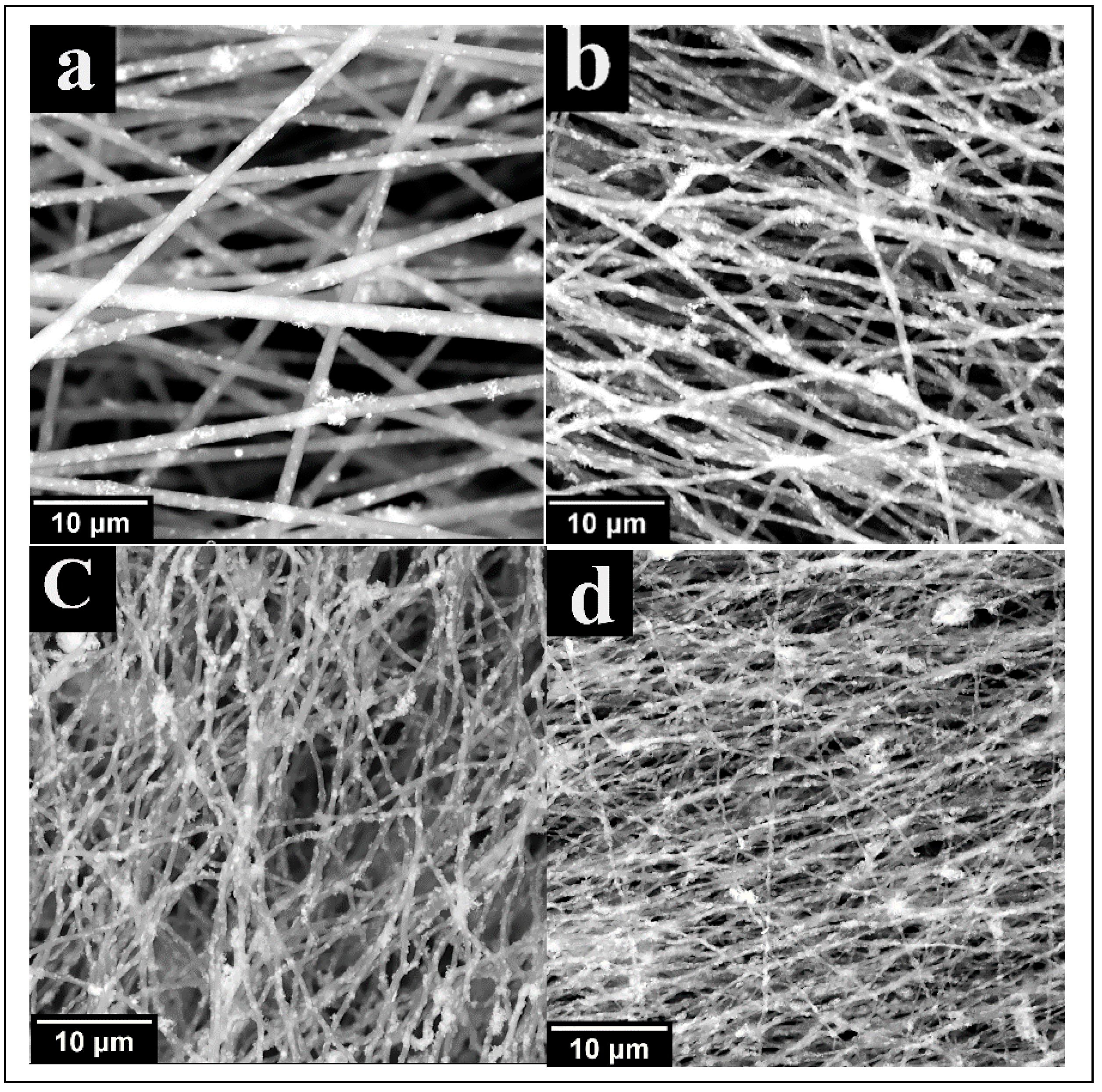
To understand the morphological changes during heat treatments, SEM characterization was carried out for all fibers, subjected to different temperatures (Figure 1). As-spun fibers were straight and regular with limited segregation of Si nano-particles to the surface. After heat treatment, the fibers begun to shrink due to the evaporation of volatile compounds. The reduction in fiber size lowers their ability to hold a. The fibers size reduction lowers their ability in holing a large amount of nano-particles and most of the silicon migrates to the fibers surface, which forms a protective SiC layer. In addition, the fibers become wavy with increasing the carbonization temperature.
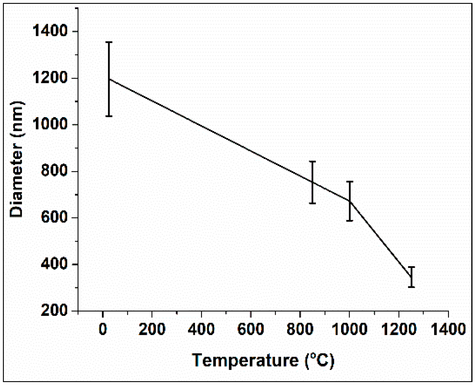
Average values from the characterization of 20 fibers was estimated using ImageJ software and the results are shown in Figure 2.
3.2. Nano-Fibers Structural Examinations
X-ray diffraction was used to confirm and track SiC formation. In general, SiC has around 200 polytypes, which are called polymorphs [28]. The two common crystalline forms of SiC are cubic (β–SiC) and hexagonal (α–SiC) forms. To identify various phases in XRD test, the interatomic spacing was calculated using the Bragg equation [29] as:
where is the wavelength of X-ray (1.5418 A°), d is interlayer distance, and is diffraction angle.
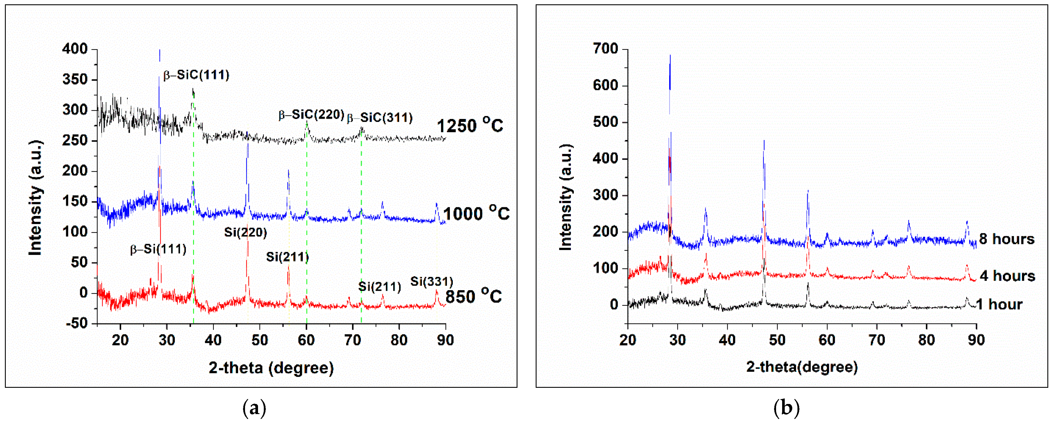
X-ray results of treated nano-fibers at different temperatures are shown in Figure 3a. For fibers treated at temperatures 1000 °C and below, the fibers have three main domains, which were carbon, SiC, and silicon. This means that SiC has begun to form at temperatures as low as 850 °C, but it was not enough to convert all silicon into SiC. Furthermore, increasing the holding times at lower temperatures did not help in reacting the remaining Si (Figure 3b). It is obvious that longer holding times improved the carbon structures in the fibers as the hump around 2θ = 26° became more characteristics toward longer times, but it does not affect the SiC to Si amounts. Carbonization at elevated temperatures (more than 1250 °C) was enough to convert all Si to SiC, which was confirmed by the X-ray results. At this temperature, the SiC major peaks were detected at 2θ = 35.5° and 72° [30], which belonged to an interatomic spacing d111 = 2.51, d220 = 1.53, and d311 = 1.309, respectively.
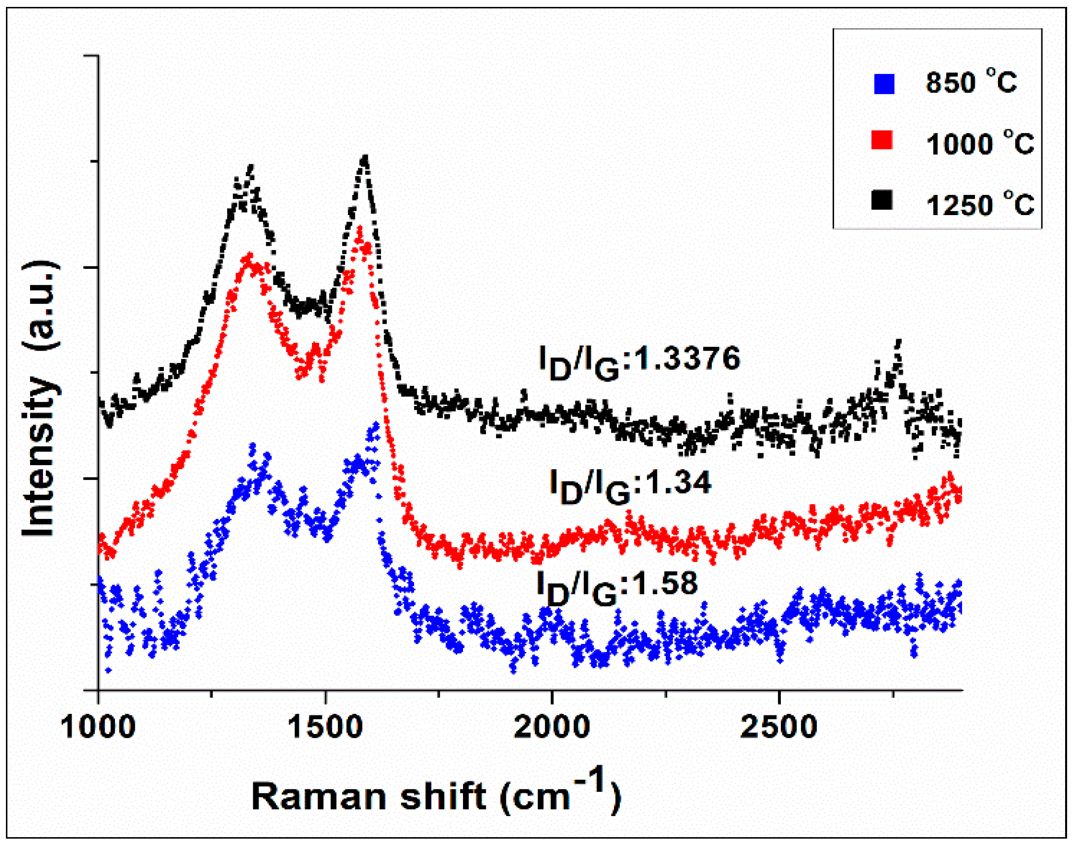
Raman spectroscopy is another powerful tool for characterizing the structure of carbon-based materials. Nano-fibers measurements were done at three different temperatures, as shown in Figure 4. The two main peaks around at 1352 and 1588 cm−1 are related to D and G band [31], respectively. Such peaks describe the molecular picture of carbon materials. The D band represents the defect in carbon structure or low ordered carbon structure in graphite domain, which means that the D band is characteristic of SP3 hybridization. On the other hand, G band represents SP2 hybridization in graphitic structure [32]. In addition, one of the important ratios in Raman spectroscopy is D to G ratio (ID/IG), which indicates the degree of graphitizability. From Figure 4, the ID/IG is inversely related to the heat treatment temperature. The ratio for higher temperatures showed a lower ratio, which means a better graphite structure. In addition, the highest heat treatment temperature (1250 °C) showed a 2D peak around 2750 cm−1.
3.3. Thermogravimetric Analysis (TGA)
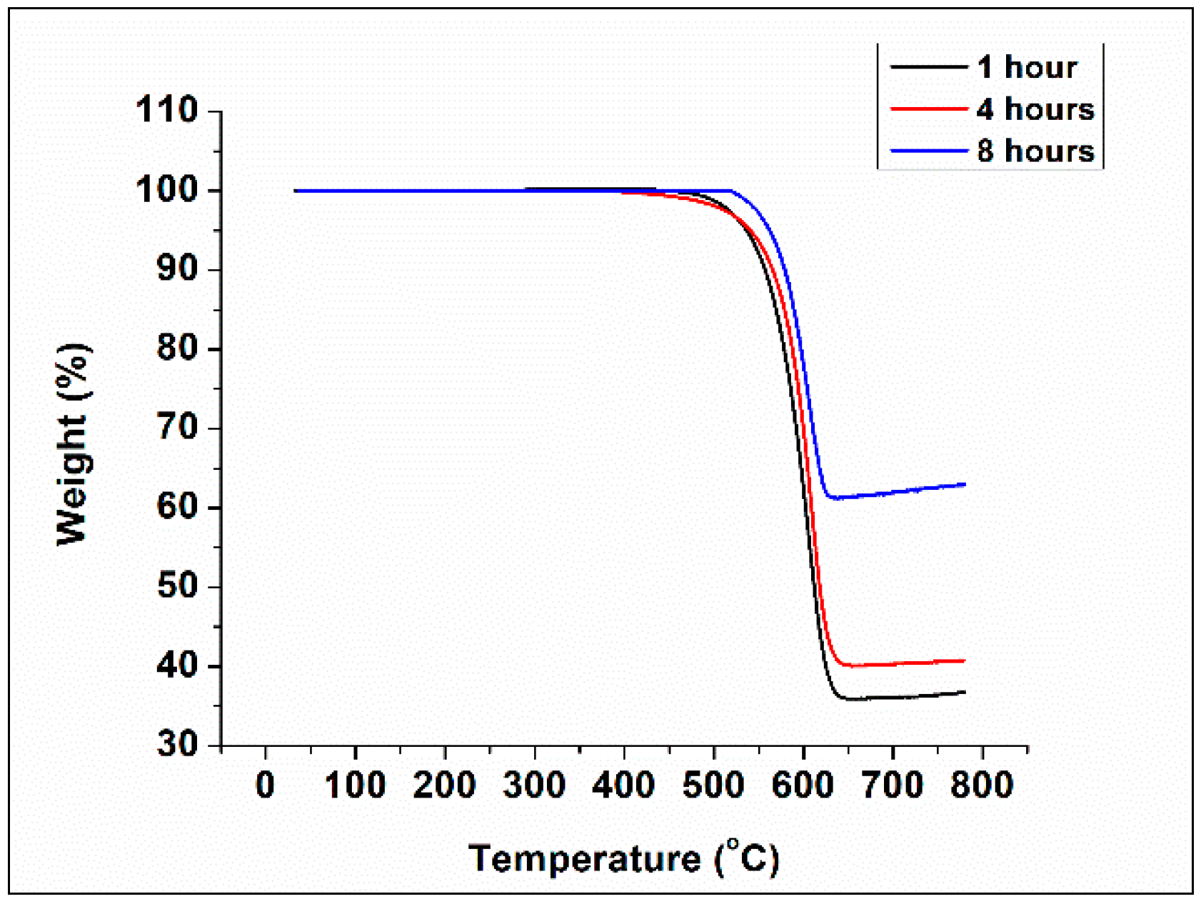
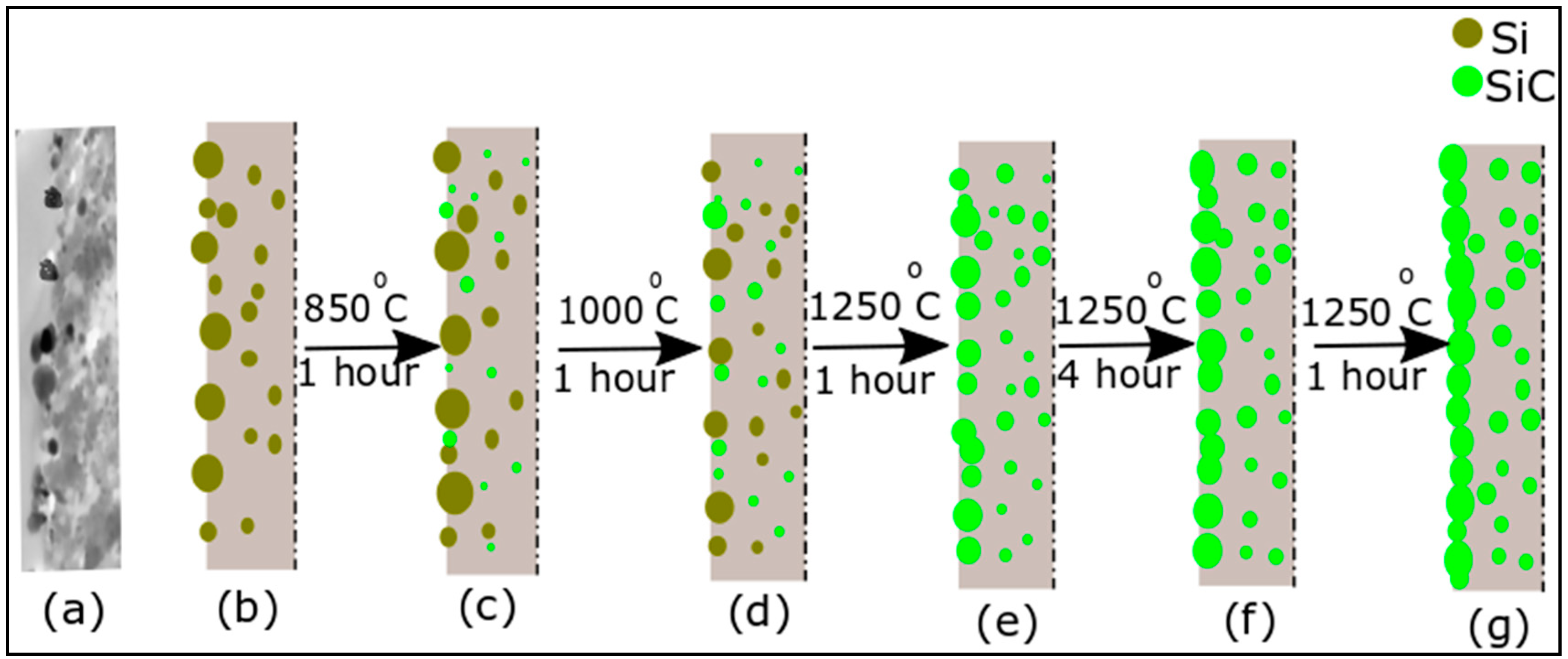
TGA results for carbonized PAN-silicon nano-fibers at different temperatures and holding times are shown in Figure 5. After carbonization, the fibers exposed to the oxidative environment to measure their thermal resistance. To do so, the TGA test was conducted in the air with a heating rate of 10 °C/min from room temperature up to 800 °C. The TGA results are summarized in Table 1. It was found that the carbonized fibers at 850 °C showed the lowest oxidation resistance and char yield. Carbonized fibers at higher temperatures showed a noticeable improvement in oxidation resistance and char yield. This confirms the effect of SiC phase growth at high temperatures in improving the carbon fibers oxidation resistance. TGA results (Figure 5) showed that the oxidation resistance of the fibers doubled due to increasing the holding time from 4 h to 8 h. The reason behind the significant improvement explained by a previously published study regarding to the silicon particle distribution [33]. It was confirmed experimentally using TEM (Figure 6a) and numerically that most of the large silicon nano-particles were located on fibers skin and the small particles were distributed randomly. This means that the intensity of silicon, initially, on the wall was higher than the center Figure 6b. Silicon atoms began to combine with C to form SiC around 850, which results in the consumption of Si, as shown in Figure 6c,d. After 1250 °C, the whole silicon was consumed and converted to SiC Figure 6e–g). The long holding times (Figure 6f) showed the highest oxidation resistance as the SiC formed a continuous silicon carbide coating layer in addition to the reinforcing effect within the fibers. TGA results confirm that the current method is an excellent and cheap way of protecting carbon fibers. Prakash et al. [34] improved the oxidation resistance of carbon fibers by achieving 16% char after coating CFs with SiC nanowires as compared with 0% char for uncoated carbon fibers. Zhou et al. [35] improved the carbon fibers oxidation resistance by growing silicon carbide on carbon fibers using catalysis chemical vapor deposition (CCVD), which increased the char yield to around 40%. In our observation, we have maximum 60% char for hybrid carbon-SiC nano-fibers.
3.4. Mechanical Test
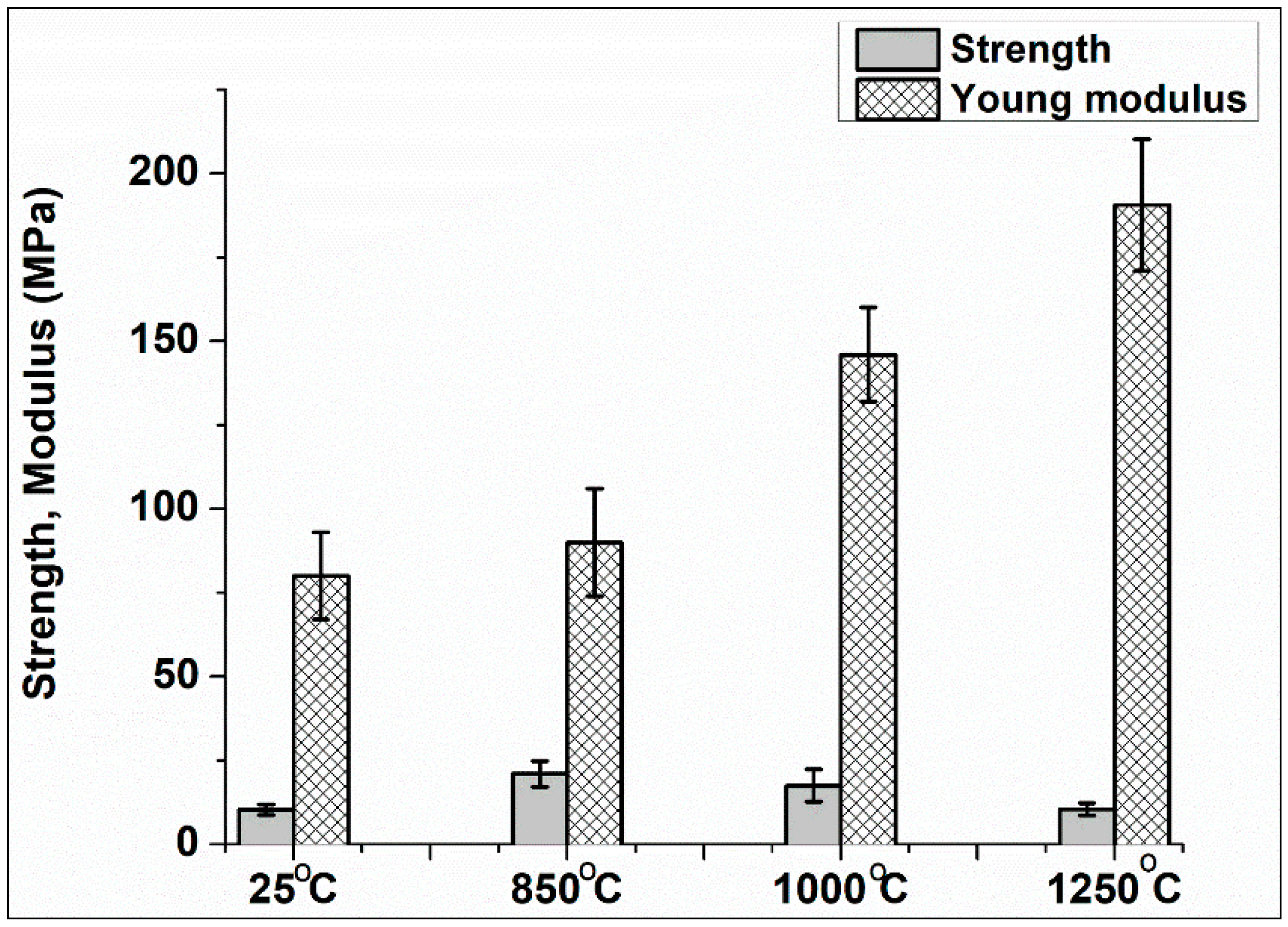
The mechanical properties of fiber mats instead of single fibers were used to avoid the challenges that are related to single fibers measurements. The fibers mat consisting of several microns thick was cut into strips to measure the fibers tensile strength. The effect of carbonization temperature on fibers mechanical properties was measured and is shown in Figure 7. The tensile strength increased from 10 MPa to 21 MPa after carbonizing the material to 850 °C. After this temperature, the strength of carbonized samples begun to decline due to ceramic phase formation, which has lower strength. Slope of the stress-strain curve showed a continuous increase with increasing the temperature due to the SiC growth which gives the material more ceramic character.
4. Conclusions
Polyacrylonitrile (PAN) and silicon (Si) nano-particles were used to fabricate Carbon-Silicon Carbide (C-SiC) hybrid nano-fibers. The heat treatment temperatures and holding times played a key role in changing the microstructure and the resulting thermal and mechanical properties. Complete conversion of silicon to SiC happened at 1250 °C, which means that, below this temperature, three phases co-exist (SiC, Si, and C), as confirmed from X-ray results. Therefore, the char yield was boosted with increasing the carbonization temperatures and soaking time due to SiC phase growth, which works as coating and reinforcing phase. An excellent char yield around 60% was recorded for carbon hybrid fibers with 8 h holding time at 1250 °C. Such observation provides a high oxidation protection for carbon fibers with low cost. Furthermore, the slope of the stress-strain curve increased its values with raising the heat treatment temperatures; however, the highest strength was recorded for lower carbonization temperature.
Author Contributions
S.M.N.A. performed and designed the experiment, analyzed the data, and provided the draft manuscript. K.L. supervised the work, reviewed and edited the manuscript.
Funding
This research received no external funding.
Conflicts of Interest
The authors declare no conflict of interest.
References
- Tong, Y.; Wang, X.; Su, H.; Xu, L. Oxidation kinetics of polyacrylonitrile-based carbon fibers in air and the effect on their tensile properties. Corros. Sci. 2011, 53, 2484–2488. [Google Scholar] [CrossRef]
- Park, S.-J.; Heo, G.-Y. Precursors and Manufacturing of Carbon Fibers BT—Carbon Fibers; Park, S.-J., Ed.; Springer: Dordrecht, The Netherlands, 2015; pp. 31–66. ISBN 978-94-017-9478-7. [Google Scholar]
- Huang, X. Fabrication and Properties of Carbon Fibers. Materials 2009, 2, 2369–2403. [Google Scholar] [CrossRef] [Green Version]
- Lu, P.; Huang, Q.; Mukherjee, A.; Hsieh, Y.-L. SiCO-doped Carbon Fibers with Unique Dual Superhydrophilicity/Superoleophilicity and Ductile and Capacitance Properties. ACS Appl. Mater. Interfaces 2010, 2, 3738–3744. [Google Scholar] [CrossRef]
- Fukuoka, H.; Ueno, S.; Aramata, M.; Okada, T.; Hamaya, N.; Maeda, T. Graphite-Silicon Carbide Composite and Making Method. U.S. Patent 12/055985, 2 October 2008. [Google Scholar] [CrossRef]
- Feng, L.; Xie, N.; Zhong, J. Carbon Nanofibers and Their Composites: A Review of Synthesizing, Properties and Applications. Materials 2014, 7, 3919–3945. [Google Scholar] [CrossRef] [PubMed] [Green Version]
- De Rosa, I.M.; Sarasini, F.; Sarto, M.S.; Tamburrano, A. EMC Impact of Advanced Carbon Fiber/Carbon Nanotube Reinforced Composites for Next-Generation Aerospace Applications. IEEE Trans. Electromagn. Compat. 2008, 50, 556–563. [Google Scholar] [CrossRef]
- Al-Qureshi, H.A. Automobile leaf springs from composite materials. J. Mater. Process. Technol. 2001, 118, 58–61. [Google Scholar] [CrossRef]
- Tarfaoui, M.; El Moumen, A.; Lafdi, K. Progressive damage modeling in carbon fibers/carbon nanotubes reinforced polymer composites. Compos. Part B Eng. 2017, 112, 185–195. [Google Scholar] [CrossRef]
- Tual, N.; Carrere, N.; Davies, P.; Bonnemains, T.; Lolive, E. Characterization of sea water ageing effects on mechanical properties of carbon/epoxy composites for tidal turbine blades. Compos. Part A Appl. Sci. Manuf. 2015, 78, 380–389. [Google Scholar] [CrossRef]
- Ali, A.H.; Mohamed, H.M.; Benmokrane, B.; ElSafty, A. Theory-based approaches and microstructural analysis to evaluate the service life-retention of stressed carbon fiber composite strands for concrete bridge applications. Compos. Part B Eng. 2019, 165, 279–292. [Google Scholar] [CrossRef]
- Pervaiz, M.; Sain, M.M. Carbon storage potential in natural fiber composites. Resour. Conserv. Recycl. 2003, 39, 325–340. [Google Scholar] [CrossRef]
- Luan, C.; Yao, X.; Liu, C.; Lan, L.; Fu, J. Self-monitoring continuous carbon fiber reinforced thermoplastic based on dual-material three-dimensional printing integration process. Carbon N. Y. 2018, 140, 100–111. [Google Scholar] [CrossRef]
- Liu, C.; Lafdi, K. Fabrication and characterization of carbon nanofibers from polyacrylonitrile/pitch blends. J. Appl. Polym. Sci. 2017, 134, 45388. [Google Scholar] [CrossRef]
- Xu, Z.; Gao, C. Graphene fiber: A new trend in carbon fibers. Mater. Today 2015, 18, 480–492. [Google Scholar] [CrossRef]
- Morgan, B.A.B.; Matters, M.; Issue, V. Polymer-Clay Nanocomposites : Design and Application of Multi-Functional Materials. Mater. Matters 2011, 2, 20–25. [Google Scholar]
- Xu, F.; Wu, D.; Fu, R.; Wei, B. Design and preparation of porous carbons from conjugated polymer precursors. Mater. Today 2017, 20, 629–656. [Google Scholar] [CrossRef]
- Al-Ajrah, S.; Lafdi, K.; Liu, Y.; Le Coustumer, P. Fabrication of ceramic nanofibers using polydimethylsiloxane and polyacrylonitrile polymer blends. J. Appl. Polym. Sci. 2017, 135, 45967. [Google Scholar] [CrossRef]
- Schöppl, O.; Ruess, G.; Lengauer, W.; Liersch, A.; Köttritsch, H. Polymer Precursor Ceramics and Their Applications; SKF Science Days: Steyr, Austria, 2004. [Google Scholar]
- Ji, L.; Jung, K.-H.; Medford, A.J.; Zhang, X. Electrospun polyacrylonitrile fibers with dispersed Si nanoparticles and their electrochemical behaviors after carbonization. J. Mater. Chem. 2009, 19, 4992–4997. [Google Scholar] [CrossRef]
- Huang, Z.M.; Zhang, Y.Z.; Kotaki, M.; Ramakrishna, S. A review on polymer nanofibers by electrospinning and their applications in nanocomposites. Compos. Sci. Technol. 2003, 63, 2223–2253. [Google Scholar] [CrossRef]
- Shao, C.; Kim, H.-Y.; Gong, J.; Ding, B.; Lee, D.-R.; Park, S.-J. Fiber mats of poly(vinyl alcohol)/silica composite via electrospinning. Mater. Lett. 2003, 57, 1579–1584. [Google Scholar] [CrossRef]
- Han, P.; Yuan, T.; Yao, L.; Han, Z.; Yang, J.; Zheng, S. Copper Nanoparticle-Incorporated Carbon Fibers as Free-Standing Anodes for Lithium-Ion Batteries. Nanoscale Res. Lett. 2016, 11, 172. [Google Scholar] [CrossRef] [Green Version]
- Dadvar, S.; Tavanai, H.; Morshed, M. Fabrication of nanocomposite PAN nanofibers containing MgO and Al2O3 nanoparticles. Polym. Sci. Ser. A 2014, 56, 358–365. [Google Scholar] [CrossRef]
- Lee, S.-H.; Yun, S.-M.; Kim, S.J.; Park, S.-J.; Lee, Y.-S. Characterization of nanoporous β-SiC fiber complex prepared by electrospinning and carbothermal reduction. Res. Chem. Intermed. 2010, 36, 731–742. [Google Scholar] [CrossRef]
- Kancheva, M.; Toncheva, A.; Manolova, N.; Rashkov, I. Enhancing the mechanical properties of electrospun polyester mats by heat treatment. Express Polym. Lett. 2015, 9, 49–65. [Google Scholar] [CrossRef] [Green Version]
- Rošic, R.; Pelipenko, J.; Kocbek, P.; Baumgartner, S.; Bešter-Rogač, M.; Kristl, J. The role of rheology of polymer solutions in predicting nanofiber formation by electrospinning. Eur. Polym. J. 2012, 48, 1374–1384. [Google Scholar] [CrossRef]
- Chikvaidze, G.; Mironova-Ulmane, N.; Plaude, A.; Sergeev, O. Investigation of silicon carbide polytypes by Raman spectroscopy. Latv. J. Phys. Tech. Sci. 2014, 51, 51–57. [Google Scholar] [CrossRef]
- Kim, S.Y.; Kim, B.-H.; Yang, K.S.; Kim, K.-Y. The formation of silica nanoparticles on the polyacrylonitrile-based carbon nanofibers by graphene via electrospinning. Mater. Lett. 2012, 71, 74–77. [Google Scholar] [CrossRef]
- Yue, Y. Synthesis of Silicon Carbide Fibers From Polycarbosilane by Electrospinning Method. Master’s Thesis, Clemson University, Clemson, SC, USA, 2014. [Google Scholar]
- Kaniyoor, A.; Ramaprabhu, S. A Raman spectroscopic investigation of graphite oxide derived graphene. AIP Adv. 2012, 2, 32183. [Google Scholar] [CrossRef] [Green Version]
- Lu, P.; Huang, Q.; Mukherjee, A.; Hsieh, Y.-L. Effects of polymer matrices to the formation of silicon carbide (SiC) nanoporous fibers and nanowires under carbothermal reduction. J. Mater. Chem. 2011, 21, 1005–1012. [Google Scholar] [CrossRef]
- Al-Ajrash, S.M.N.; Lafdi, K.; Vasquez, E.S.; Chinesta, F.; Le Coustumer, P. Experimental and Numerical Investigation of the Silicon Particle Distribution in Electrospun Nanofibers. Langmuir 2018, 34, 7147–7152. [Google Scholar] [CrossRef]
- Prakash, J.; Dasgupta, K.; Kumar, B.; Ghosh, S.K.; Chakravartty, J.K. Role of SiC nanowire coating on oxidation behavior of carbon fibers: Kinetic and thermodynamic study. Surf. Coat. Technol. 2014, 259, 637–646. [Google Scholar] [CrossRef]
- Zhou, W.; Long, L.; Xiao, P.; Li, Y.; Luo, H.; Hu, W.; Yin, R. Silicon carbide nano-fibers in-situ grown on carbon fibers for enhanced microwave absorption properties. Ceram. Int. 2017, 43, 5628–5634. [Google Scholar] [CrossRef]
Figure 1.
Scanning electron microscope (SEM) graphs of treated fibers (holding time 4 h) at (a) 25 °C, (b) 850 °C, (c) 1000 °C, (d) 1250 °C.
Figure 1.
Scanning electron microscope (SEM) graphs of treated fibers (holding time 4 h) at (a) 25 °C, (b) 850 °C, (c) 1000 °C, (d) 1250 °C.

Figure 2.
Relationship between fibers diameter and heat treatment temperature. Data points correspond to the average from 20 fibers. Error bars correspond to one standard deviation with respect to the average value.
Figure 2.
Relationship between fibers diameter and heat treatment temperature. Data points correspond to the average from 20 fibers. Error bars correspond to one standard deviation with respect to the average value.

Figure 3.
X-ray results of nano-fibers mat heat treated at (a) three distinct temperatures and one hour holding time, (b) 1000 °C at three distinct holding times.
Figure 3.
X-ray results of nano-fibers mat heat treated at (a) three distinct temperatures and one hour holding time, (b) 1000 °C at three distinct holding times.

Figure 4.
Raman spectroscopy of carbon fibers at three distinct temperatures.

Figure 5.
Thermal gravity analysis (TGA) curves of hybrid carbon fibers at different soaking times at 1250 °C.
Figure 5.
Thermal gravity analysis (TGA) curves of hybrid carbon fibers at different soaking times at 1250 °C.

Figure 6.
SiC nucleation and growth of SiC phase from silicon and carbon phases (a) TEM image of as-spun PAN-Si nano-fibers, (b) as-spun PAN-Si nano-fibers illustration, (c) SiC nucleation, (d) SiC growth, (e) conversion of all Si to SiC, (f) SiC grain coarsening, (g) overlapping the adjacent SiC grains on the fibers wall forming protective ceramic coating

Figure 7.
The relationship between mechanical properties and heat treatment temperature.


Table 1.
Influence of heat treatment temperature and soaking time on hybrid carbon fibers char yield.
Table 1.
Influence of heat treatment temperature and soaking time on hybrid carbon fibers char yield.
| Heat Treatment Temperature (°C) | Holding Time (Hours) | Char Yield (%) |
|---|---|---|
| 850 | 1 | 29 |
| 1000 | 1 | 33 |
| 1250 | 1 | 37 |
| 4 | 41 | |
| 8 | 62 |
© 2019 by the authors. Licensee MDPI, Basel, Switzerland. This article is an open access article distributed under the terms and conditions of the Creative Commons Attribution (CC BY) license (http://creativecommons.org/licenses/by/4.0/).
Share and Cite
MDPI and ACS Style
Al-Ajrash, S.M.N.; Lafdi, K. Hybrid Carbon Nano-Fibers with Improved Oxidation Resistance. Ceramics 2019, 2, 25-33. https://doi.org/10.3390/ceramics2010003
AMA Style
Al-Ajrash SMN, Lafdi K. Hybrid Carbon Nano-Fibers with Improved Oxidation Resistance. Ceramics. 2019; 2(1):25-33. https://doi.org/10.3390/ceramics2010003
Chicago/Turabian StyleAl-Ajrash, Saja M. Nabat, and Khalid Lafdi. 2019. "Hybrid Carbon Nano-Fibers with Improved Oxidation Resistance" Ceramics 2, no. 1: 25-33. https://doi.org/10.3390/ceramics2010003