The Optimization of Marine Diesel Engine Rotational Speed Control Process by Fuzzy Logic Control Based on Particle Swarm Optimization Algorithm


Faculty of Marine Engineering, Vietnam Maritime University, Haiphong 180000, Vietnam
Future Internet 2018, 10(10), 99; https://doi.org/10.3390/fi10100099
Submission received: 3 September 2018
/
Revised: 21 September 2018
/
Accepted: 28 September 2018
/
Published: 4 October 2018
(This article belongs to the Special Issue New Perspectives in Intelligent Transportation Systems and Mobile Communications towards a Smart Cities Context)
Abstract
:The marine main diesel engine rotational speed automatic control plays a significant role in determining the optimal main diesel engine speed under impacting on navigation environment conditions. In this article, the application of fuzzy logic control theory for main diesel engine speed control has been associated with Particle Swarm Optimization (PSO). Firstly, the controller is designed according to fuzzy logic control theory. Secondly, the fuzzy logic controller will be optimized by Particle Swarm Optimization (PSO) in order to obtain the optimal adjustment of the membership functions only. Finally, the fuzzy logic controller has been completely innovated by Particle Swarm Optimization algorithm. The study results will be represented under digital simulation form, as well as comparison between traditional fuzzy logic controller with fuzzy logic control–particle swarm optimization speed controller being obtained.
1. Introduction
Fuzzy logic control was proposed by Prof. Zadeh in 1965. The Mamdani fuzzy inference system was displayed to conduct a steam engine and boiler control process by linguistic rule [1,2]. On the other hand, fuzzy logic control has been expressed by if-then rules with the human language. Besides that, the mathematical model does not need to establish in design process of a fuzzy logic controller. So, the fuzzy logic control is a good robustness. Its advantage is easy application, because there is no need an intensive information technology programmers and it has been used widely in science and industry. The rules and membership functions of a fuzzy logic controller are definitely based on empirical experience or knowledge database. Fuzzy logic control has been reported to be successfully to use a number of complex and nonlinear processes. Fuzzy logic control is occasionally proved to be more robust and their performances that are less sensitive to parametric variations than conventional controllers [3,4]. Zhou, et al., have analyzed the fuzzy control rules and membership function parameters [2]. H. Wei, et al., 2009 have compared between rigid feedback and constant-speed feedback control system, and construct a fuzzy control system of diesel speed. This comparison will result that the fuzzy control method is a feasible method and better than the other methods [5]. Some other researches of scholars and scientists have been indicated the benefits to apply fuzzy logic control in optimizing service system of diesel engine. S. Simani and M. Bonfe’ have established fuzzy modelling and control system of the air system for diesel engine [6]. David J. McGowan et al. have integrated governor control for a diesel by the detailed implementation of real-time fuzzy logic speed control for a standby diesel-generating set [7]. Tran et al., had established the diesel engine rotational speed automatic controller by using fuzzy-PID logic control theory [8]. On the other hand, the study of fuzzy logic theory has also conducted through some articles. Jafari et al., had modeled the uncertain nonlinear systems along with fuzzy differential equations (FDEs) by fuzzy set [9]. Moreover, the determination of uncertainty property through Z-number of fuzzy equation has also been investigated by Jafari et al. [10]. Furthermore, Particle Swarm Optimization (PSO) algorithm has been used to get the optimal values from fuzzy logic control rules. PSO has been based on a metaphor of social interaction. PSO’s function conducts to look up a space by adjusting the trajectories of individual vectors and called ‘Particles’. The movement of points in multidimensional space is conceptualized by Particles. The positions of their own previous best performances and the best previous performance of their neighbors are determined stochastically by individual particles. One another side, two notable improvements have been referred as the initial PSO, which attempt to strike a balance between the two conditions. The first condition is introduced by Shi and Eberhart which has been used like as an extra ‘inertia weight’ term and to scale down the velocity of each particle and this term is typically decreased linearly throughout a run [11]. The left condition has been introduced by Clerc and Kennedy involves a ‘constriction factor’ where the entire right side of the formula is weighted by a coefficient [12]. On the other hand, the combination between fuzzy logic control and PSO has been conducted by some researches at individual field. Fevrier. V, et al. have introduced evolutionary methodology for combining Particle Swarm Optimization (PSO) and Genetic Algorithms (GAs) when using fuzzy logic control for decision making [13]. In this study, the Particle Swarm model allows an infinite number of ways in which the balance between exploration and convergence can be controlled. Particle Swarm Optimization algorithm is studied to choose the membership functions and the fuzzy control rules. In addition, the ranges of membership functions in controller are very important to conduct an accuracy control process due to the expert experiences or knowledge database play an important role in designing the control model. The combination between fuzzy logic control and PSO will help the control process more realizably when considering the control objective is diesel engine speed. This study has been divided into sections, in particular, Section 1, Introduction; Section 2, Methodology with fuzzy logic control theory and Particle Swarm Optimization (PSO); Section 3, Case study with modelling of main diesel engine rotational speed control by fuzzy logic and optimization of diesel engine speed control process by PSO; Section 4, Results; and, Section 5, Conclusions.
2. Methodology
2.1. Fuzzy Logic Control Theory
Fuzzy logic control was first proposed by Lotfi A.Zadeh who comes from the University of Carlifornia at Berkeley in his paper in 1965 [14]. In his paper, he has elaborated on his ideas in a 1973 paper in which he proposed the concept of “liguistic variables”. The content of his paper has been equated to a variable defined as a fuzzy set [15]. Fuzzy logic idea is similar to the human being’s feeling and inference process. Unlike the classical control theory that is a point-to-point control but fuzzy logic control has approached a range-to-point or range-to-range control.
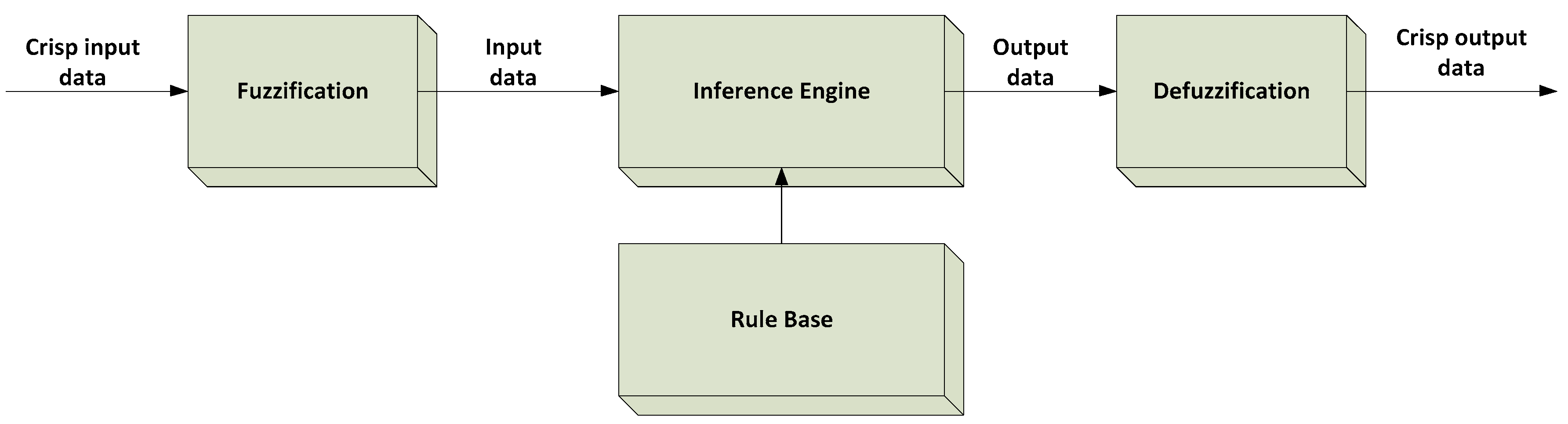
In Figure 1, the certain fuzzy logic control system will have four functional blocks: Fuzzification, inference engine, rule base, and defuzzification. The initial signal is a crisp input data that will be admitted into the fuzzy logic control system. After that, this signal will be converted into fuzzy input data by the fuzzification block. The inference engine or decision making logic will determine how the fuzzy logic control operations are displayed (Sup-Min inference), and together with the rule base will identify the output parameters of each fuzzy control by If-Then rules. The combination will be converted to crispy values with the defuzzification block. The output crisp value can be computed by the center of gravity or the weighted average. The fuzzy control system is based on the rule system that is on expert knowledge and including fuzzy sets and fuzzy algorithms. In summary, from Figure 1, fuzzy logic control process will be conducted following function blocks. The first block is fuzzification and membership functions that understands and characterizes the system behavior by using knowledge and experience. The second block is fuzzy control rule with directly designing the control algorithm with fuzzy rules in which they describe the principles of the controller’s regulation in terms of the relationship between its inputs and outputs. The last block is defuzzification to simulate and debug the design.
The variables in fuzzy logic system could have the values in range of 0 and 1. Hence, the type of logic system is able to address these values of the variables to set between completely true and completely false. The variables are called as linguistic variables and each linguistic variable is appointed by a membership function along with has a certain degree of membership function at a particular instance. In practice, membership functions have multiple different types, such as the triangular waveform, trapezoidal waveform, Gaussian waveform, bell-shaped waveform, sigmoidal waveform, and S-curve waveform [16]. In order to choose accurate type of membership functions needs to depend on the actual applications. However, in this research case, it needs to have significant dynamic variation in a short time, so a triangular or trapezoidal waveform would be utilized.
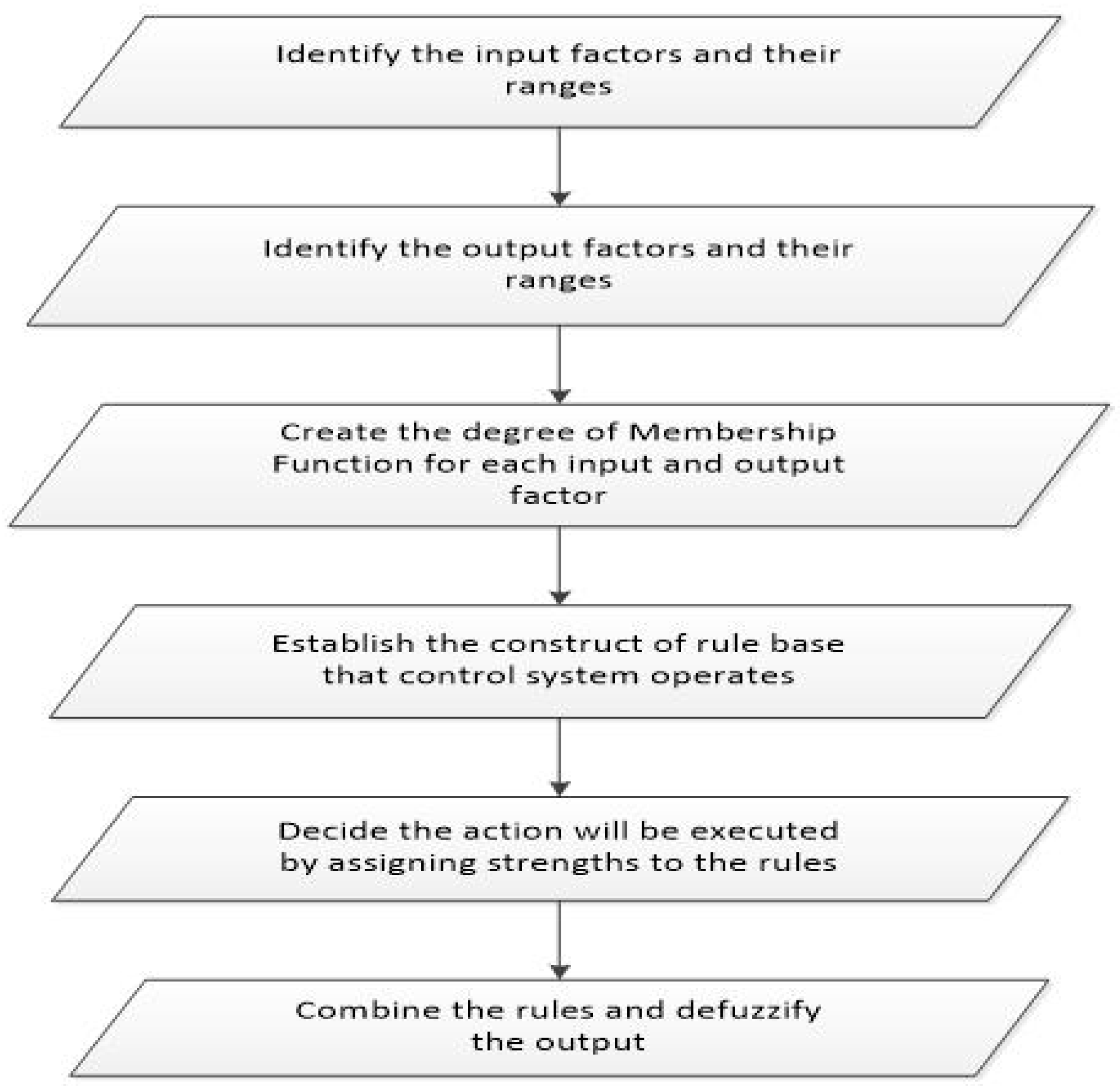
Whether the performance is not satisfactory then users only modify some fuzzy rules and resume. Fuzzy logic control has been applied widely to the control process through fuzzy linguistic descriptions [17,18]. In order to process, in detail, the inputs to get the outputs reasoning, there are six works that need to do in applying to fuzzy logic control theory (Figure 2).
The first work needs to identify the input factors along with their ranges. This work completely bases on experimental knowledge of fuzzy logic control theory. The second work is also similar with the first work but instead of determining the output factors. The output factors can include one factor or more, but in this study, the output factor only has one factor: diesel engine speed (n).
The third work must conduct to create the degree of membership function for each input factor and output factor. The fourth work is an establishment of the construct of rule base in aims with controlling system operates. The next work needs to give the action that will be executed by assigning strengths to rule base of controlling system. The final is a combination the rules and defuzzification of the output factor.
2.1.1. Fuzzification
Fuzzification in designing a fuzzy logic controller is established by the state variables representing the system dynamic performance. The system dynamic performance consists of the input variable signal to control. Fuzzy logic control theory uses the linguistic variables, such as low, medium, high, big, small, positive, negative, zero, etc. instead of using numerical simulation method. The fuzzification is known as converting a numerical variable (real number or crisp variables) into a linguistic variable (fuzzy number). The fuzzy sets are characterized by membership functions that cover all universe of discourse. The triangular, trapezoidal, Gaussian, etc are different form of fuzzy sets [16].
2.1.2. Rule Base
The rule base is defined as If-Then format and called the conditional control rule. Under the supporting computer program that is able to execute the rules and calculate a control signal. The calculation is definitely based on error (e) and change in error (de) of the measured input signals.
2.1.3. Inference Engine
The inference engine or inference operation comprises an information processing system such as a computer program. The inference engine is similar to the human brain and evaluates the fuzzy rules. The output signal is generated completely to base on each fuzzy control rule. There are different types of inference engine for example max-min method, max-dot product, etc. [19].
2.1.4. Defuzzification
The defuzzification is reversible process of fuzzification. In order to use the fuzzy logic controller needs the output in a linguistic variable (fuzzy number). Depending on real requirements, the linguistic variables must be transformed to the crisp output [20,21]. There are many defuzzification methods, but the most common use methods are Center of Gravity (COG), Bisector of Area (BOA), and Mean of Maximum (MOM).
2.2. Particle Swarm Optimization Algorithm
Eberhart and Kennedy [22] have foundated the theory of Particle Swarm Optimization (PSO). This method is based on stochastic optimization and the social behavior of bird flock or fish school.
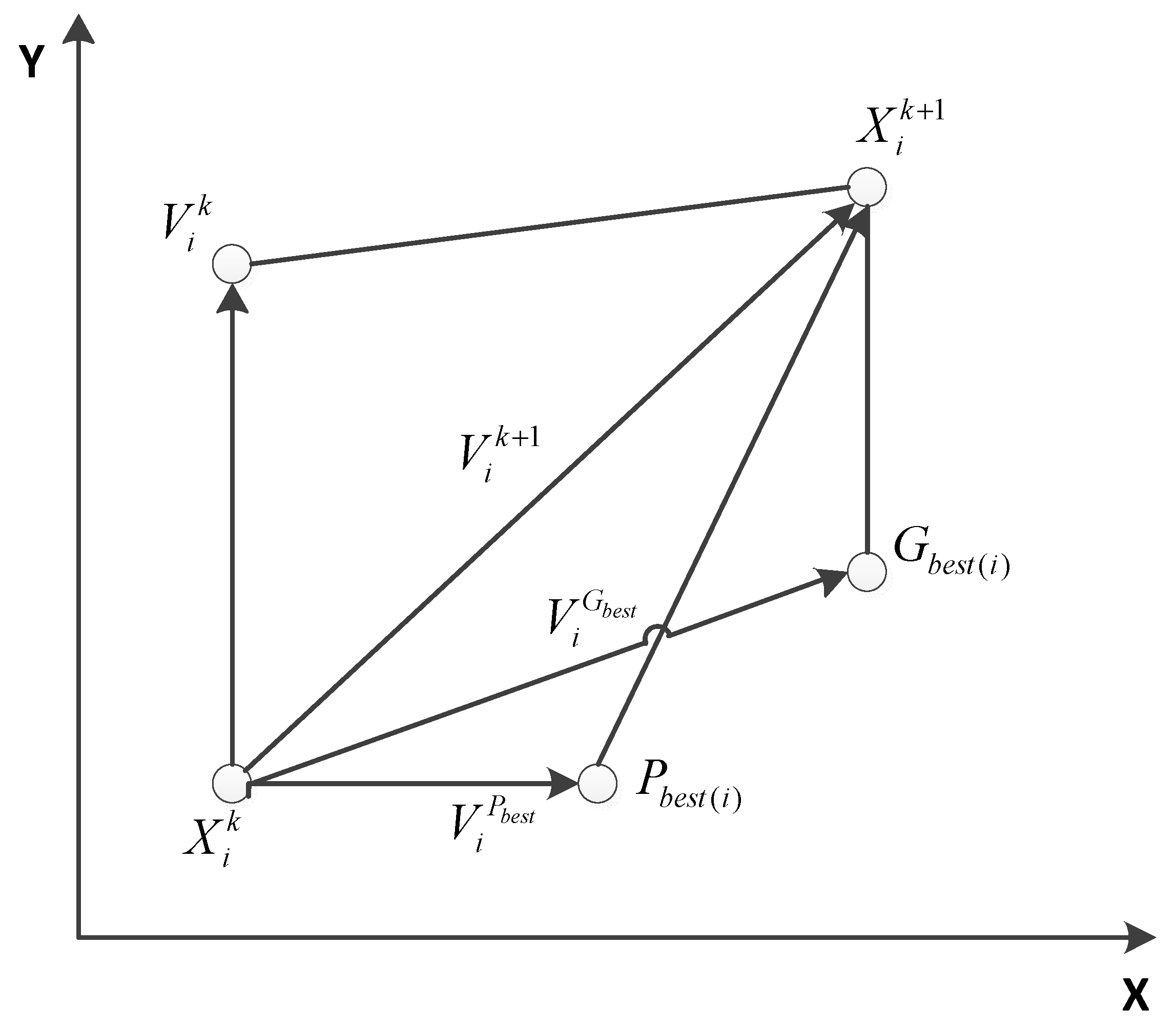
Each particle plays an important role in the use of Particle Swarm Optimization method. The particles will associate together after that they look for the best solution or fitness function value. The fitness function value is called as Pbest. The fitness function value will correspond to the best location (Lbest). Especially, a particle takes all of the topological neighbors. In this case, the best value will be a global best value and it is known as Gbest (Figure 3) [13].
Where:
is the current position;
is the modified position;
is the current velocity;
is the modified velocity;
is the velocity of Pbest; and,
is the velocity of Gbest.
The Particle Swarm Optimization (PSO), which is known as an evolutionary computation algorithm, is different from other one such as Genetic Algorithms (GAs). The search space of PSO algorithm is carried out by a population. The simulation of bird flock or fish school behavior is known as PSO method. The discovery and previous experience of bird flock behavior in the finding food have made an effective evolutionary computation algorithm, like the PSO method. So, particle particle is called as each companion in the population, which is called swarm swarm. Swarm is assumed to ‘fly’ over the search space in order to find promising regions of the landscape.
Each particle is allocated with a random velocity initially and its location is adjusted according to its own previous best (Pbest) and the global best (Gbest). On the other hand, the velocity change is weighted by random terms with separate random numbers being generated for acceleration toward the two best solutions (Pbest and Gbest). The procedures of PSO algorithm have been showed in Figure 4.
- ➢
- Initialization process: Generate a population of particles and allocate a velocity to each particle randomly.
- ➢
- Ø Evaluation process: Update the best locations of particles and calculate the optimization fitness function.
- ➢
- Velocity and location update: Change the location of each particle by means of updating its own velocity as well as the particle will be adjusted dramatically.
- ➢
- The updating process of velocity and location at each particle can be realized through Equations (1) and (2).
i = 1, 2, ..., n; and m = 1, 2, ..., d;
n is the number of particles in the group;
d is the dimension of the group;
k is the number of iterations of the current particle;
w is the inertia weight factor;
Pbest is the previous best;
Gbest is the global best;
X is the location of the particle;
V is the velocity of the particle;
c1, c2 are the acceleration coefficients; and,
r1, r2 are the random numbers between 0 and 1.
The assumption is a basic definition of Particle Swarm Optimization (PSO). In PSO algorithm, a flock of particles are put into the d-dimensional search space with randomly in order to choose velocities and positions that are known as their best values (Pbest) and the position in the d-dimensional space. Furthermore, the velocity of each particle is adjusted according to its own flying experience and the other particle’s flying experience. It is assumed that the j-th particle is represented as xi = (xi1, xi2, ..., xid) in the d-dimensional space then the best previous position of the i-th particle will be recorded and is described like this:
Pbest i = (Pbest i1, Pbest i2, ..., Pbest in)
In where, the index of best particle among all of the particles is Gbest d. The velocity of i-th particle is specified as vi = (vi1, vi2, ..., vid). Additionally, the modified velocity and the position of each particle are computed following Equation (1) and (2).
3. Case Study
Modeling of Main Diesel Engine Rotational Speed Control by Fuzzy Logic Control Theory
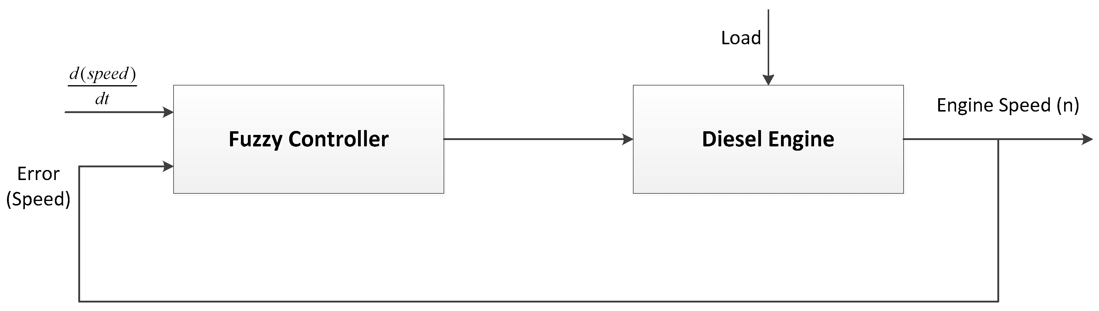
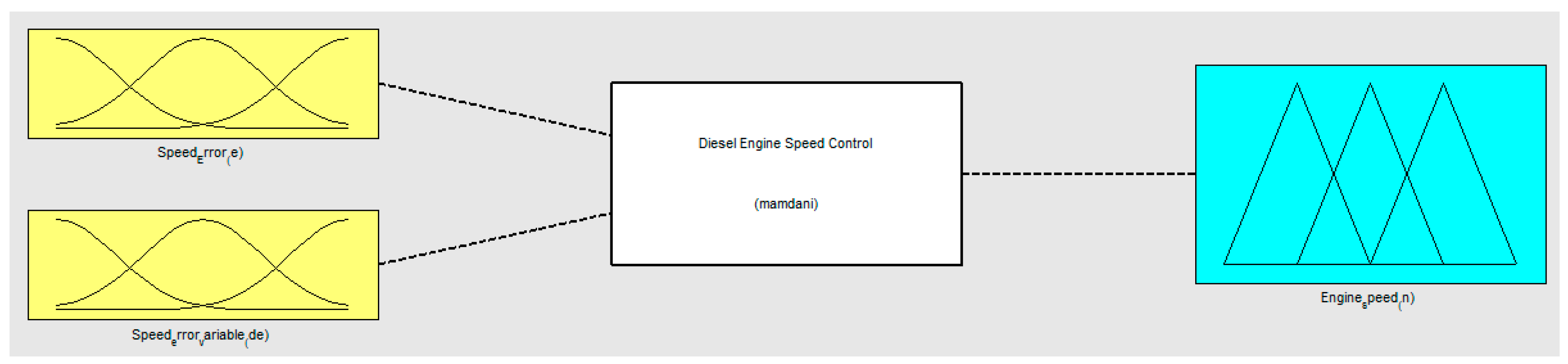
Fuzzy controller includes functional blocks (fuzzification, rule base, inference engine, and defuzzification), and it has been described in Figure 1. In this research, the objective of controlling process is a diesel engine speed. In fact, marine diesel engine operates in hard condition under impacting on navigation environment, like as wind, wave, tidal current, etc. All of the external factors will be made the instability of engine when it works. Diesel engine speed is an important factor that it will decide the engine working condition when external load is variable. Furthermore, fuel consumption of engine always associates with engine speed. In a result, diesel engine speed controller is very necessary to help engine works effectively. In Figure 5, the modelling of diesel engine speed automatic control has been presented. Speed error and variable speed error are the input signals of fuzzy controller. Speed error will be compared between reference speed and speed feedback signal that took from output source of diesel engine (revolution on engine speed).
In order to conduct the fuzzy control process, the definition of speed error (e) and variable speed error (de) as the input signals of the fuzzy controller. Besides that, the output signals of fuzzy controller must also be determined as engine speed. The linguistic set of e, de, and the engine speed is NB, NM, NS, ZO, PS, PM, and PB.
In where: NB = Negative Big, NM = Negative Medium, NS = Negative Small, ZO = Zero, PS = Positive Small, PM = Positive Medium, and PB = Positive Big.
The discourse universe of input signals and output signal is a range of [0, 1]. In addition, triangular membership function has been adopted as the membership functions of input signals and output signal of fuzzy controller, respectively.
Since each input signal of linguistic set has seven members inclusding NB, NM, NS, ZO, PS, PM, and PB, then the control rule construction of fuzzy controller will include 49 rules, and they have been described in Table 1.
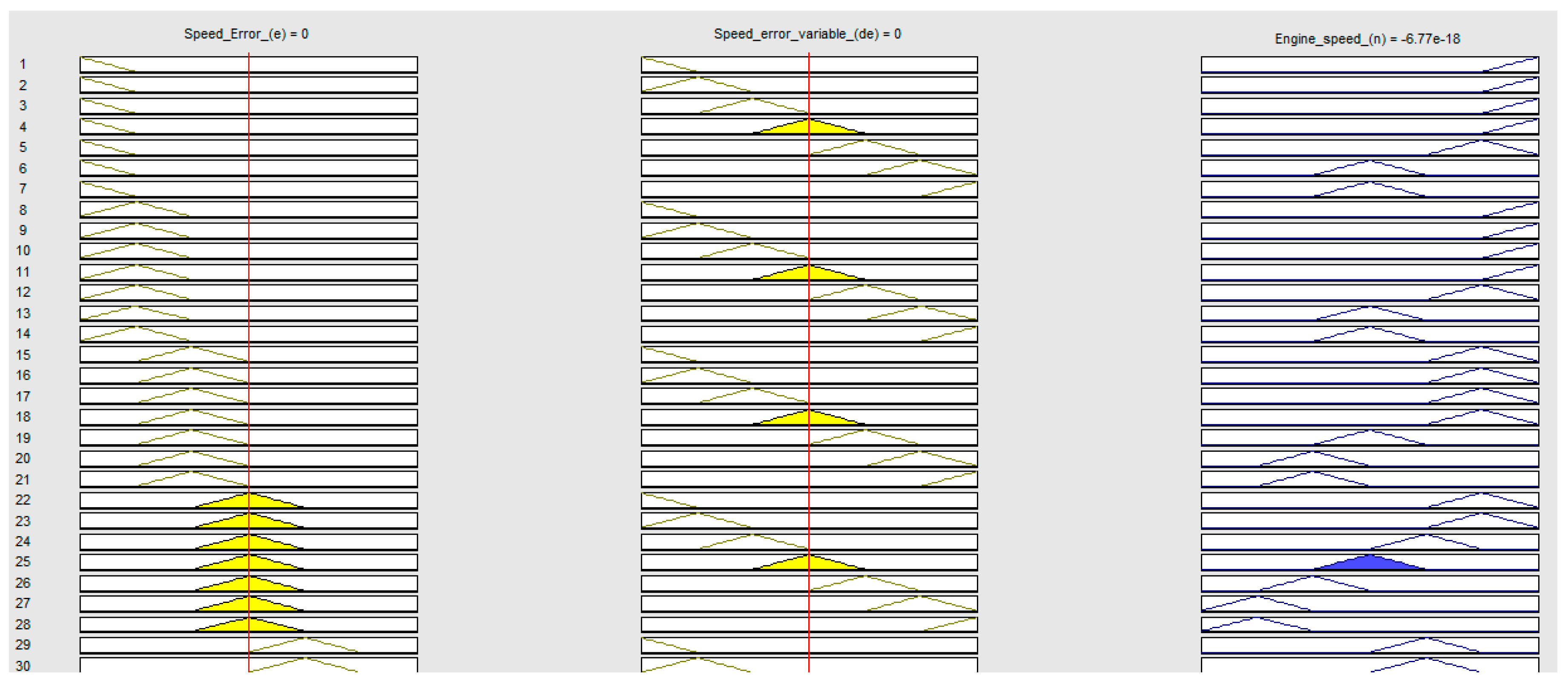
On the other hand, the fuzzy controller has two input signals then the antecedent of each control rule will have two parts. Equation “And” will be used to combine the two parts of the antecedent to gain a signal number that represents the result of the antecedent for that rule. So, the result will be applied in the implication process to achieve the fuzzy set of the output. The implication method has been used as “And”. It means that the minimum value will be compared with aims in obtaining the desired output value in fuzzy control process. So, the implication process will be implemented for each rule in fuzzy control rules. The simulation process of fuzzy logic controller for diesel engine speed has been identified in Figure 6, Figure 7 and Figure 8 below.
1. If Speed error (e) is NB and Speed error variable (de) is NB then Engine speed (n) is PB.
2. If Speed error (e) is NB and Speed error variable (de) is NM then Engine speed (n) is PB.
3. If Speed error (e) is NB and Speed error variable (de) is NS then Engine speed (n) is PB.
4. If Speed error (e) is NB and Speed error variable (de) is ZO then Engine speed (n) is PB.
5. If Speed error (e) is NB and Speed error variable (de) is PS then Engine speed (n) is PM.
⋮
48. If Speed error (e) is PB and Speed error variable (de) is PM then Engine speed (n) is NB.
49. If Speed error (e) is PB and Speed error variable (de) is PB then Engine speed (n) is NB.
The application of Particle Swarm Optimization (PSO) algorithms for fuzzy logic controller has been described in Figure 9. The initial populations are the first step of Particle Swarm Optimization (PSO) algorithms. Especially, the population is composed of the chromosomes that are real codes. Hence, the “fitness function” is generated by the corresponding judgment of a population. Moreover, the “fitness function” is the performance index of a population. In particular, the value of “fitness function” is bigger and then the performance is better. Equation (4) is represented for “fitness function”.
where:
PI is the fitness value;
e is the speed error; and,
K is a coefficient.
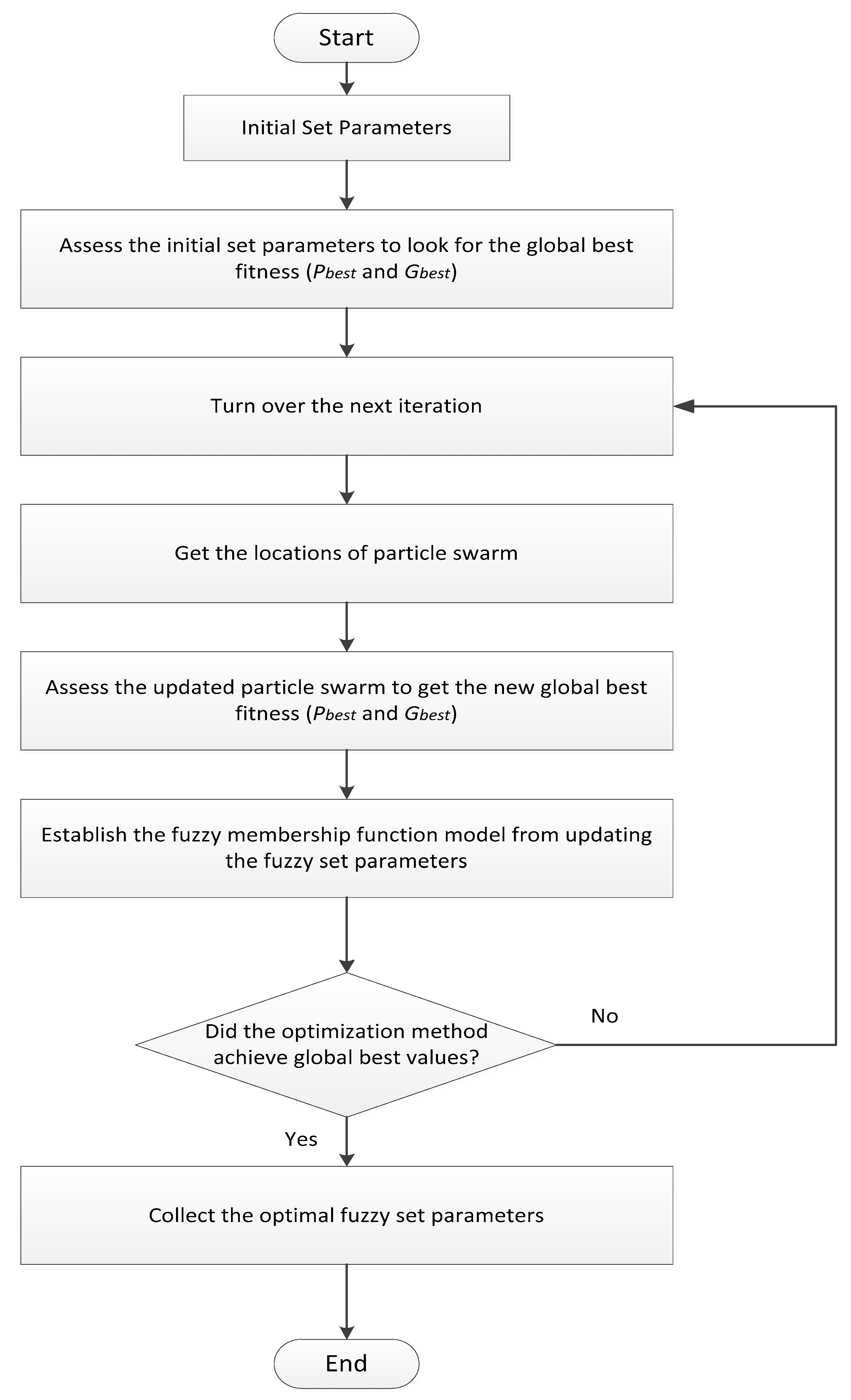
Afterward, the fitness function has been determined then the fitness value and the number of generation will be considered if or not the applicable process stopped (maximum iteration number reached?). In addition, the calculation of the Pbest of each particle and Gbest of population (the best movement of all particles). In a result, the update of velocity, position, Pbest, and Gbest of particles will approach a new best position (best chromosome in our proposition) (Figure 10).
On the other hand, the performance of a fuzzy model can be measured by the mean-square-error (mse). In the case of two model estimates, for instance, the one with the smaller mse with respect to the experimental model has a better match. The mse is defined by Equation (5) that is used as the fitness measure for the PSO algorithm implementation.
In where, and represents the actual value and the estimated value at data point k, respectively; and, q is the number of data points.
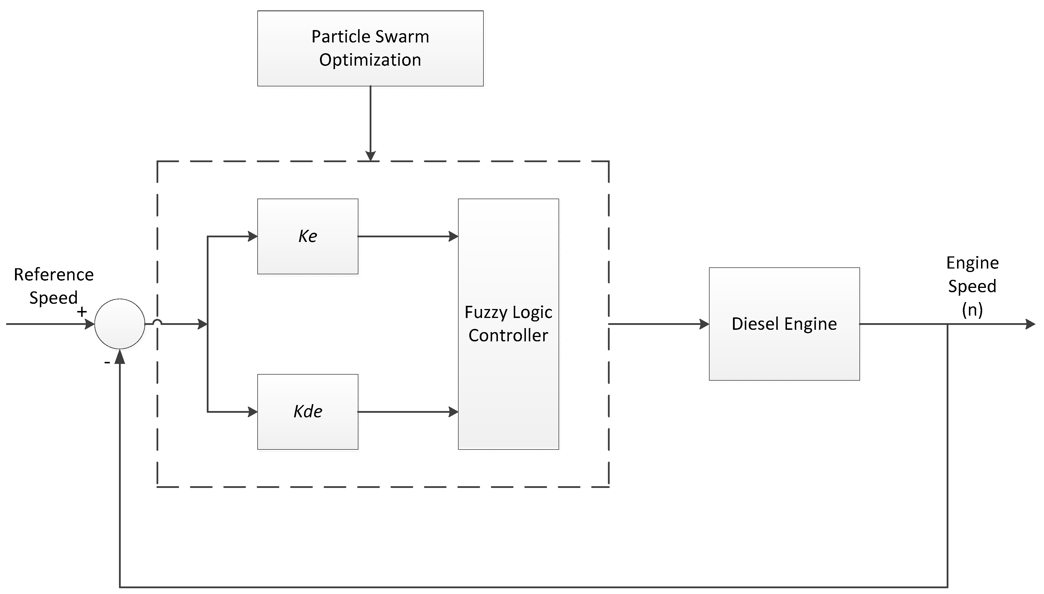
In this study, the chromosomes of the particle swarm optimization (PSO) algorithms will consist of three elements (Figure 11). Firstly, the range of membership functions includes Ke and Kde coefficients. Secondly, the shape of membership functions includes following coefficients e1~e7, de1~de7, and n1~n7. Thirdly, the fuzzy inference rules include r1~r49. On the other hand, the diesel engine speed output is thereby such that the steady state error of response is zero.
Moreover, the fuzzy inference rules from r1~r49 are corresponded to number 1 (Negative Big—NB), 2 (Negative Medium—NM), 3 (Negative Small—NS), 4 (Zero—Z), 5 (Positive Small—PS), 6 (Positive Medium—PM), and 7 (Positive Big—PB).
Table 2 represents the fuzzy inference rules with PSO algorithms.
The main diesel engine speed controller has been established throughout the fuzzy logic control theory. This controller completely responses to the targets of main diesel engine speed control when considering the navigation environment conditions. Furthermore, fuzzy logic controller has been designed based on experience knowledge from the fact on ships that use the diesel engine speed controller (governor) for main diesel engines with specific types like MAN B&W and SULZER. In addition, based on the actual operation situation, the main diesel engine speed controller has been acted appropriately for adjusting the fuel rack handle in aim with keeping engine speed constantly.
Although the conventional controller bases on the accuracy of the system model and parameters, fuzzy logic controller uses the different strategies for adjusting diesel engine speed under impacting on the external environment factors. Fuzzy logic controller proposes the experiences and linguistic definitions. Moreover, if there is not enough knowledge about control process, the fuzzy logic controller might give satisfactory results. The aim of fuzzy logic controller is to minimize the speed error. Besides that, the change of speed error plays a virtal role to define the controller input. Consequently, fuzzy logic controller uses the speed error and change of speed error for linguistic knowledge which are generated from the control rules.
The speed error is computed with comparison between reference speed and speed signal feedback from speed output of main diesel engine. Both speed error and change of speed error are fuzzy controller inputs. From output signal of fuzzy logic controller will act on actuator and then make the movement of fuel control position on main diesel engine. In reality, the fuel rack handle will decide the diesel engine speed. If the fuel control position is at an increasing level, then diesel engine speed will increase and vice versa.
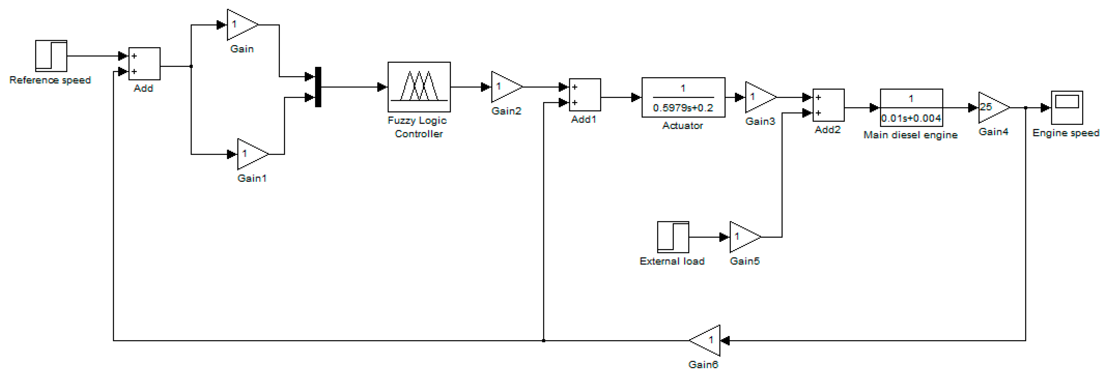
In Figure 12, the model of main diesel engine speed controller has been built on Simulink/Matlab environment. To establish this model, the input signals and output signal of fuzzy logic controller have been defined. The speed error and change of speed error are input signals of controller. The main diesel engine speed is output signal of controller. The output signal of controller will act on actuator through transfer function under form , as well as the main diesel engine with transfer function . The transfer functions of actuator and main diesel engine have been assumed with testing the main diesel engine speed controller based on fuzzy logic control theory. On the other hand, the external load has been added in order to change the diesel engine speed. It likes as the navigation environment factor impacts. From the model of diesel engine speed controller has been established on Simulink/Matlab environment that appropriately verified the fuzzy logic controller for main diesel engine speed control.
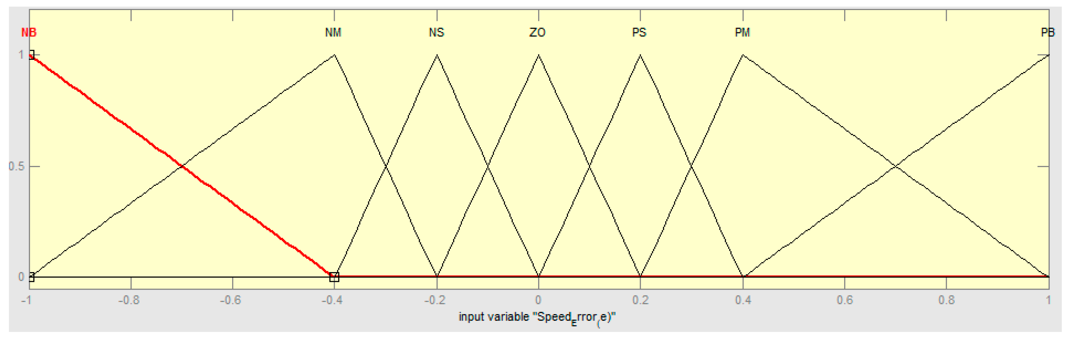
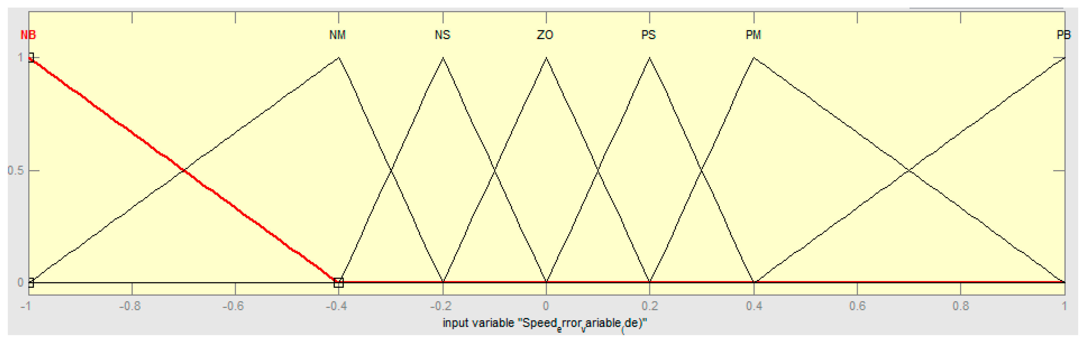
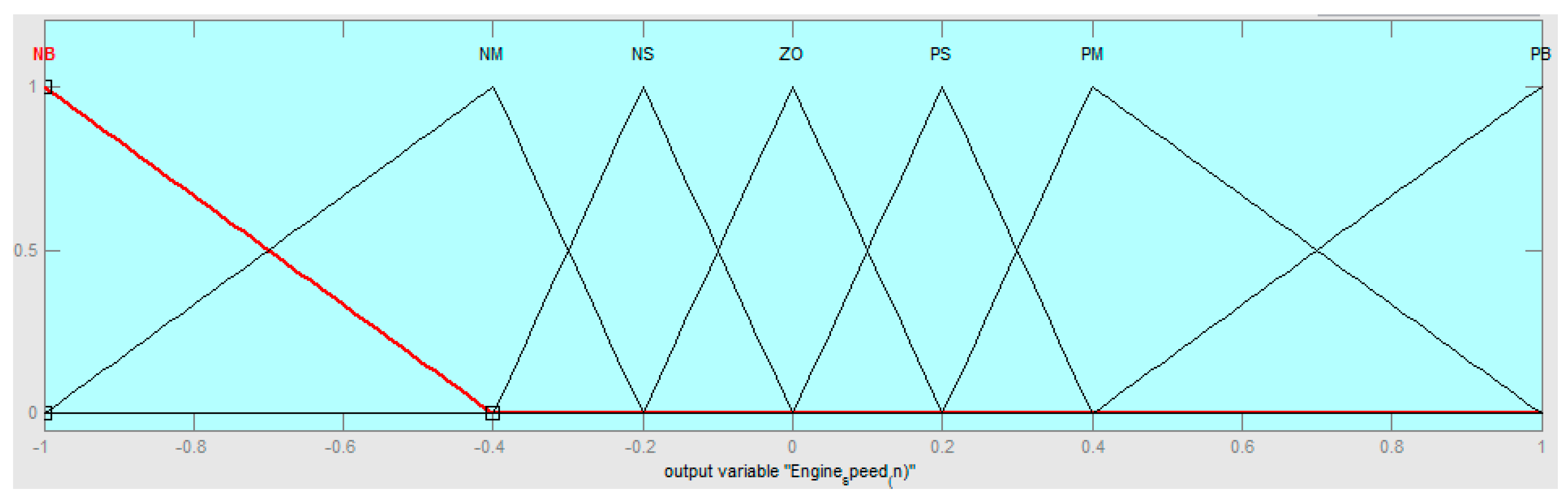
In this study, the fuzzy membership functions of diesel engine speed controller are optimized by Particle Swarm Optimization (PSO) algorithms. PSO algorithms will find out the optimal positions, as well as the best ranges of each variable in diesel engine speed controller. Based on coefficients of particle swarm optimization (PSO) algorithms in Table 3, the shapes of fuzzy membership functions (e, de, n) are represented in Figure 13, Figure 14 and Figure 15.
4. Results
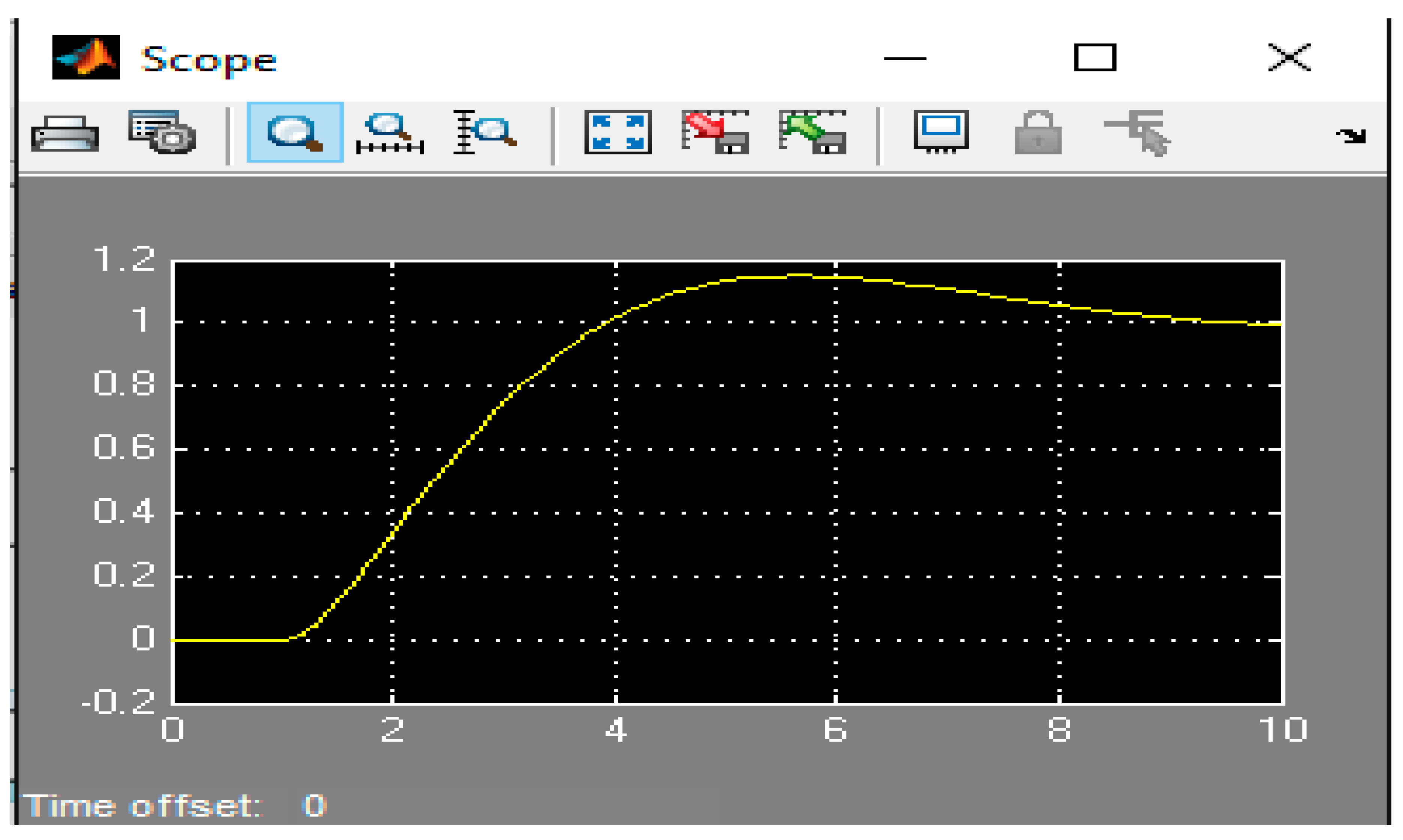
The diesel engine speed will be controlled through fuzzy logic controller when the assumptions have been given out in modelling of diesel engine speed controller on Simulink/Matlab (Figure 12). The simulation process of the main diesel engine speed control has been represented in Figure 16 below. In where, the horizontal axis presents the time of adjusting (Unit: second) and the vertical axis presents the change of diesel engine speed in controlling process.
Consequently, the simulation process has been indicated that main diesel engine speed will be adjusted after having action signal from actuator under 1 (second). In the case of research, if there is a change of main diesel engine speed when the external load impacts then fuzzy logic controller will give a control signal in order to keep constant for the desired speed of operator.
It assumes that if the diesel engine speed increases then fuzzy controller will give a signal to reduce diesel engine speed and vice versa. In Figure 16 the diesel engine speed always keeps at constant level when comparing with the initial reference speed. When there is a change of diesel engine speed then diesel engine speed controller will control speed to gain the constant level like as the initial reference speed. On the other hand, the change level of diesel engine speed in this case is a range of [−2, 2] and it can vary if the external load and output signal (gain 4) are set at different levels corresponding to the test case.
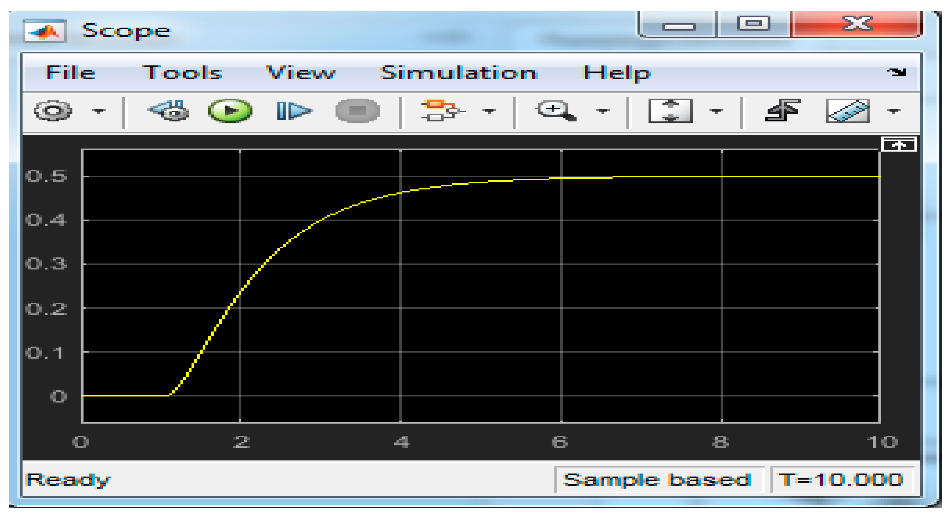
In this case, the speed adjusting range of diesel engine has been reduced through reference speed in controlling model (Figure 12). Despite engine speed changes, the proposed speed controller also keeps constantly according to the diesel engine speed control curve in Figure 17. So, this one presents accurately in establishing this proposed model.
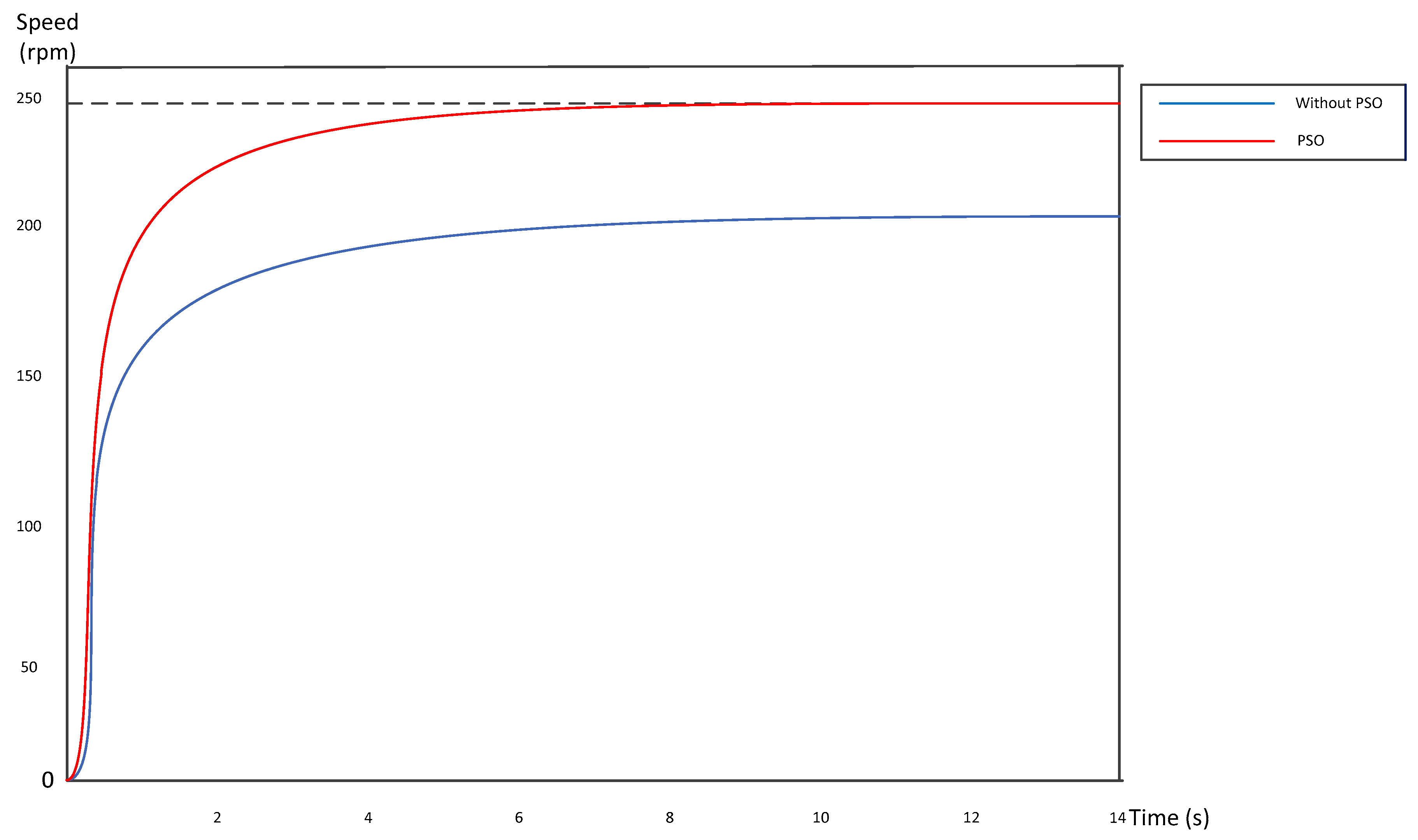
Moreover, diesel engine speed controller based on fuzzy logic control that is optimized by machine learning, in particular, particle swarm optimization (PSO) algorithms. So, particle swarm optimization (PSO) algorithms have been found the best ranges of membership functions of diesel engine speed controller. In Figure 18, the characteristic curves are represented with a comparison between diesel engine speed controller without using PSO algorithms and controller using PSO algorithms.
Consequently, the diesel engine speed controller using PSO algorithms have significantly benefits when compared with traditionally fuzzy logic controller when applying into this research. The range of diesel engine speed control has been enlarged when applying into particle swarm optimization (PSO) algorithms. In Figure 18, the traditional fuzzy logic controller has just limited at speed range 200 rpm (revolution per minute) but this range will be increased in 250 rpm when applying to PSO algorithms.
5. Conclusions
The diesel engine speed control plays a vital role in maintaining the desired speed of operators. The application of modern control theory like as fuzzy logic control is necessary in condition of the external loads changing. The fuzzy logic controller for main diesel engine speed has been brought a lot of advantages instead of using traditional PID (Proportional–Integrative–Derivative) controller. Furthermore, this study has associated with particle swarm optimization (PSO) algorithms along with fuzzy logic controller for main diesel engine on ships that achieved benefits. The range of diesel engine speed has been improved, as well as the control process is more stable. Moreover, the fuzzy logic controller combined with PSO algorithm has represented more advantages when comparing with other traditional controllers, such as PID logic controller and fuzzy logic controller. The proposed controller has been designed according to fuzzy rule base of fuzzy logic controller and automatically adjust the membership function. The advantages of the fuzzy logic controller based PSO algorithm are more convenient than fuzzy logic controller since this proposed method is able to adjust automatically the membership function of input signal and output signal. This one is an optimal point comparing with fuzzy logic controller without using the PSO algorithm. However, the use of this proposed method also meets the drawnbacks such as more complex, requiring the high degree of operators. From these research results, the author will continue the development of proposed method not only fuzzy based PSO algorithm, but also fuzzy combined with GA (Genetic Algorithm) or fuzzy combined with neural networks artificial.
Acknowledgments
The author wants to kindly thank to Key Laboratory of Marine Power Engineering & Technology (Ministry of Transportation), School of Energy and Power Engineering, Wuhan University of Technology, 1178 Heping Road, Wuhan 430063, Hubei, China supports to complete this research.
Conflicts of Interest
The author declares no conflicts of interest
References
- Yen, J.; Langari, R. Fuzzy Logic: Intelligence, Control, and Information; Prentice-Hall: Upper Saddle River, NJ, USA, 1999. [Google Scholar]
- Zhou, Y.S.; Lai, L.Y. Optimal Design for Fuzzy Controllers by Genetic Algorithms. IEEE Trans. Ind. Appl. 2000, 36, 93–97. [Google Scholar] [CrossRef]
- Jiang, J. Optimal Gain Scheduling Controller for a Diesel Engine. In Proceedings of the IEEE Conference on Control Applications, Vancouve, BC, Canada, 13–16 September 1994. [Google Scholar]
- Astrom, K.; Hagglund, T. PID Controllers: Theory, Design and Tuning, Instrument Society; ISA: Research Triangle Park, NC, USA, 1995. [Google Scholar]
- Wei, H.; Min, R.; Yingqi, T. A Fuzzy Control System of Diesel Generator Speed. In Proceedings of the 2009 Asia-Pacific Power and Energy Engineering Conference, Wuhan, China, 27–31 March 2009. [Google Scholar]
- Simani, S.; Bonfe, M. Fuzzy Modelling and Control of the Air System of a Diesel Engine. Adv. Fuzzy Syst. 2009, 2009, 450259. [Google Scholar] [CrossRef]
- McGowan, D.J.; Morrow, D.J.; Fox, B. Integrated Governor Control for a Diesel—Generating Set. IEEE Trans. Energy Convers. 2006, 21, 476–483. [Google Scholar] [CrossRef]
- Tran, T.A.; Yan, X.; Yuan, Y. Marine Engine Rotational Speed Control Automatic System Based on Fuzzy PID Logic Control. In Proceedings of the 4th International Conference on Transportation Information and Safety (ICTIS 2017), Banff, AB, Canada, 8–10 August 2017; pp. 1099–1104. [Google Scholar]
- Jafari, R.; Yu, W.; Li, X.; Razvarz, S. Numerical Solution of Fuzzy Differential Equations with Z-numbers Using Bernstein Neural Networks. Int. J. Comput. Intell. Syst. 2017, 10, 1226–1237. [Google Scholar] [CrossRef]
- Jafari, R.; Li, X.; Yu, W. Numerical Solution of Fuzzy Equations with Z-numbers Using Neural Networks. Intell. Autom. Soft Comput. 2017, 85, 1–7. [Google Scholar] [CrossRef]
- Shi, Y.; Eberhart, R. A Modified Particle Swarm Optimizer. In Proceedings of the International Conference on Evolutionary Computation—The IEEE World Congress on Computational Intelligence, Anchorage, AK, USA, 4–9 May 1998; pp. 69–73. [Google Scholar]
- Clerc, M.; Kennedy, J. The Particle Swarm-explosion, Stability, and Convergence in a Multidimensional Complex Space. IEEE Trans. Evolut. Comput. 2002, 6, 58–73. [Google Scholar] [CrossRef]
- Valdez, F.; Melin, P.; Castillo, O. Evolutionary Method Combining Particle Swarm Optimization and Genetic Algorithms using Fuzzy Logic for Decision Making. In Proceedings of the IEEE International Conference on Fuzzy Systems, Jeju Island, Korea, 20–24 August 2009. [Google Scholar]
- Zadeh, A.L. Fuzzy Sets. Inf. Control 1965, 8, 338–353. [Google Scholar] [CrossRef]
- Zadeh, A.L. Outline of a New Approach to the Analysis of Complex Systems and Decision Processes. IEEE Trans. Syst. Man Cybern. 1973, 1, 28–44. [Google Scholar] [CrossRef]
- Aissaoui, A.G.; Tahour, A. Application of Fuzzy Logic in Control of Electrical Machines. Available online: http://www.intechopen.com/books/fuzzy-logic-controls-conceptstheories-andapplications/-application-of-fuzzy-logic-in-control-ofelectrical-machines (accessed on 28 March 2012).
- Uddin, M.N.; Huang, Z.R.; Chy, M.M.I. A Simplified Self-Tuned Neuro-Fuzzy Controller Based Speed Control of an Induction Motor Drive. In Proceedings of the 2007 IEEE International Conference on Industrial Technology, Tampa, FL, USA, 24–28 June 2007. [Google Scholar]
- Pundaleek, B.H.; Manish, G.R.; Vijay Kumar, M.G. Speed Control of Induction Motor: Fuzzy Logic Controller v/s PI Controller. IJCSNS Int. J. Comput. Sci. Netw. Secur. 2010, 10, 10. [Google Scholar]
- Vas, P. Artificial Intelligence Based Drives. In Power Electronics Handbook. Rashid, M.H., Ed.; Academic Press: Cambridge, MA, USA, 2001. [Google Scholar]
- Bai, Y.; Zhuang, H.; Wang, D. Advanced Fuzzy Logic Technologies in Industrial Applications; Springer: Berlin/Heidelberg, Germany, 2006. [Google Scholar]
- Rubaai, A. Fuzzy Logic in Electric Drives. In Power Electronics Handbook; Rashid, M.H., Ed.; Academic Press: Cambridge, MA, USA, 2001. [Google Scholar]
- Kennedy, J.; Eberhart, R.C. Particle Swarm Optimization. In Proceedings of the IEEE International Conference on Neural Networks, Piscataway, NJ, USA, 27 November–1 December 1995; pp. 1942–1948. [Google Scholar]
- Allaoua, B.; Abderrahmani, A.; Brahim, G.; Nasri, A. The Efficiency of Particle Swarm Optimization Applied on Fuzzy Logic DC Motor Speed Control. Serb. J. Electr. Eng. 2008, 5, 247–262. [Google Scholar] [CrossRef]
- Wang, K.; Yan, X.; Yuan, Y. Optimizing Ship Energy Efficiency: Application of Particle Swarm Optimization Algorithm. Proc. Inst. Mech. Eng. Part M J. Eng. Marit. Environ. 2016, 1–13. [Google Scholar] [CrossRef]
Figure 1.
Block of fuzzy logic control system.

Figure 2.
The steps to create fuzzy control system.

Figure 3.
The modification of a searching points by Particle Swarm Optimization (PSO) [23].
Figure 3.
The modification of a searching points by Particle Swarm Optimization (PSO) [23].

Figure 4.
Procedures of the Particle Swarm Optimization [24].
Figure 4.
Procedures of the Particle Swarm Optimization [24].

Figure 5.
Modelling of diesel engine speed control by fuzzy logic controller.

Figure 6.
Fuzzy logic control inference.

Figure 7.
Diesel engine speed control rules.

Figure 8.
Surface of diesel engine speed control.3.2. Optimization of Main Diesel Engine Rotational Speed Control Process by Particle Swarm Optimization Algorithm.
Figure 8.
Surface of diesel engine speed control.3.2. Optimization of Main Diesel Engine Rotational Speed Control Process by Particle Swarm Optimization Algorithm.

Figure 9.
Particle Swarm Optimization to adjust membership functions.

Figure 10.
Algorithm of applying PSO to optimize fuzzy logic controller.

Figure 11.
Block diagram of fuzzy logic control with particle swarm optimization.

Figure 12.
Simulation model of marine diesel engine speed Controller.

Figure 13.
Membership function of speed error (e) optimized by PSO.

Figure 14.
Membership function of speed error variable (de) optimized by PSO.

Figure 15.
Diesel engine speed output (n) optimized by PSO.

Figure 16.
Simulation of diesel engine speed control process.

Figure 17.
Simulation of diesel engine speed controller when decreasing the setting value (Reference Speed).
Figure 17.
Simulation of diesel engine speed controller when decreasing the setting value (Reference Speed).

Figure 18.
Characteristic curves of diesel engine speed control using PSO algorithms.


Table 1.
Control rules of diesel engine speed by fuzzy logic control.
| e | NB | NM | NS | ZO | PS | PM | PB | |
|---|---|---|---|---|---|---|---|---|
| de | ||||||||
| NB | PB | PB | PM | PM | PS | ZO | ZO | |
| NM | PB | PB | PM | PM | PS | ZO | ZO | |
| NS | PB | PB | PM | PS | ZO | NM | NM | |
| ZO | PB | PB | PM | ZO | NM | NB | NB | |
| PS | PM | PM | ZO | NS | NM | NB | NB | |
| PM | ZO | ZO | NS | NM | NM | NB | NB | |
| PB | ZO | ZO | NS | NM | NM | NB | NB | |
Table 2.
Fuzzy inference rules with PSO algorithms.
| e | NB | NM | NS | ZO | PS | PM | PB | |
|---|---|---|---|---|---|---|---|---|
| de | ||||||||
| NB | r1 | r8 | r15 | r22 | r29 | r36 | r43 | |
| NM | r2 | r9 | r16 | r23 | r30 | r37 | r44 | |
| NS | r3 | r10 | r17 | r24 | r31 | r38 | r45 | |
| ZO | r4 | r11 | r18 | r25 | r32 | r39 | r46 | |
| PS | r5 | r12 | r19 | r26 | r33 | r40 | r47 | |
| PM | r6 | r13 | r20 | r27 | r34 | r41 | r48 | |
| PB | r7 | r14 | r21 | r28 | r35 | r42 | r49 |
Table 3.
Coefficients of Particle Swarm Optimization (PSO) algorithms.
| Population Size | 50 | e1, de1 and n1 | [−1, −1, −0.4] |
| Number of Iteration | 100 | e2, de2 and n2 | [−1, −0.4, −0.2] |
| wmax | 0.6 | e3, de3 and n3 | [−0.4, −0.2, 0] |
| wmin | 0.1 | e4, de4 and n4 | [−0.2, 0, 0.2] |
| c1 = c2 | 1.5 | e5, de5 and n5 | [0, 0.2, 0.4] |
| Min-offset | 200 | e6, de6 and n6 | [0.2, 0.4, 1] |
| Ke and Kde | [0.001, 0.005] | e7, de7 and n7 | [0.4, 1, 1] |
© 2018 by the author. Licensee MDPI, Basel, Switzerland. This article is an open access article distributed under the terms and conditions of the Creative Commons Attribution (CC BY) license (http://creativecommons.org/licenses/by/4.0/).
Share and Cite
MDPI and ACS Style
Tran, T.A. The Optimization of Marine Diesel Engine Rotational Speed Control Process by Fuzzy Logic Control Based on Particle Swarm Optimization Algorithm. Future Internet 2018, 10, 99. https://doi.org/10.3390/fi10100099
AMA Style
Tran TA. The Optimization of Marine Diesel Engine Rotational Speed Control Process by Fuzzy Logic Control Based on Particle Swarm Optimization Algorithm. Future Internet. 2018; 10(10):99. https://doi.org/10.3390/fi10100099
Chicago/Turabian StyleTran, Tien Anh. 2018. "The Optimization of Marine Diesel Engine Rotational Speed Control Process by Fuzzy Logic Control Based on Particle Swarm Optimization Algorithm" Future Internet 10, no. 10: 99. https://doi.org/10.3390/fi10100099
Note that from the first issue of 2016, this journal uses article numbers instead of page numbers. See further details here.