Recent Progress in the Design of 4G/5G Reconfigurable Filters
by
 , , , and
Yasir I. A. Al-Yasir
1,* ,
,
Naser Ojaroudi Parchin
1 ,
,
Raed A. Abd-Alhameed
1 ,
,
Ahmed M. Abdulkhaleq
1,2 and
and
James M. Noras
1 
1
School of Electrical Engineering and Computer Science, Faculty of Engineering and Informatics, University of Bradford, Bradford BD7 1DP, UK
2
SARAS Technology Limited, Leeds LS12 4NQ, UK
*
Author to whom correspondence should be addressed.
Electronics 2019, 8(1), 114; https://doi.org/10.3390/electronics8010114
Submission received: 22 December 2018
/
Revised: 9 January 2019
/
Accepted: 16 January 2019
/
Published: 20 January 2019
(This article belongs to the Special Issue Recent Technical Developments in Energy-Efficient 5G Mobile Cells)
Abstract
:Currently, several microwave filter designs contend for use in wireless communications. Among various microstrip filter designs, the reconfigurable planar filter presents more advantages and better prospects for communication applications, being compact in size, light-weight and cost-effective. Tuneable microwave filters can reduce the number of switches between electronic components. This paper presents a review of recent reconfigurable microwave filter designs, specifically on current advances in tuneable filters that involve high-quality factor resonator filters to control frequency, bandwidth and selectivity. The most important materials required for this field are also highlighted and surveyed. In addition, the main references for several types of tuneable microstrip filters are reported, especially related to new design technologies. Topics surveyed include microwave and millimetre wave designs for 4G and 5G applications, which use varactors and MEMSs technologies.
1. Introduction
Reconfigurable microwave filters are vital in wireless communications. Many applications require diversity in filter performance. Traditional filter banks occupy much space on circuit boards, fuelling interest in replacing them with compact tuneable filters, saving space and improving performance. The centre frequency is the only tunable parameter in most reconfigurable filters and relatively few filter designs offer other tunable parameters such as bandwidth, poles, zeros and quality factors. To select the suitable technique of reconfiguration for a given application, researchers should take into account the following parameters: operating frequency, physical size, performance and power handling. Microwave filters can be categorized in terms of the position of the poles and their effect on the insertion loss and the effect of the zeros on the characteristics of the passband. The zeros are usually distributed within the passband to give equiripple or Chebyshev characteristics. From the other side, when the poles are analysed, this kind of filter has all these positioned at DC or infinity and it is usually called an all-pole Chebyshev filter or simply a Chebyshev filter. It is worth mentioning that it is highly recommended to place poles where they are most required and also to minimise their number; each extra pole complicates systems and increases cost [1,2,3].
Some researchers have designed tuneable microwave filters using varactor diodes [4,5,6,7,8,9,10,11,12,13,14,15,16,17,18,19,20,21,22,23,24,25,26,27]. In these articles, most designs are focussed on bandpass tuneable resonators [4,5,6,7,8,9,10,11,12,13,14,15,16,17,18,19,20] and tuneable band-stop resonators using varactor diodes [21,22,23,24,25]. Only a few designs of microwave low-pass tuneable resonators and high-pass tuneable resonators are presented [26,27]. That is because of the deficiency of practical monolithic reconfigurable inductor solutions that increase the complexity of realizing a good performance for the design. In general, research into reconfigurable bandpass and band-stop resonator filters generally investigated reconfigurable frequency and bandwidth. Among a variety of prototype designs, λ/4 and λ/2 tuneable filters with varactor diodes, as well as multi-mode filters, are mostly used because of their compact size and the simplicity of the tuning circuit. For example, by using a λ/4 resonator, Hunter and Rhodes [4] presented a microstrip second-order combline filter at 3450–5000 MHz with a 3.2–5.2 dB insertion loss using striplines and varactor diodes as switches. To achieve constant impedance bandwidth, the filter was required to have electrical length at the mid-point of the frequency band. This technique also used in the design of a tuneable microstrip combline filter using stepped impedance resonators with varactor diodes [5].
Sanchez et al. presented a reconfigurable bandpass combline filter resonating at 470 MHz, adjusting the mutual coupling between the resonating elements [6]. Wang and et al. presented a planar reconfigurable combline resonator filter using varactor diodes [7]. In this design, the short-circuited end of the resonators was replaced by lumped series lines. According to this technique, the slope parameter of the introduced lines can be adjusted to achieve a constant fractional bandwidth covering a wide tuning range. Park et al. reported a second-order reconfigurable filter using varactor diodes [8].
Three different types of bandwidth responses have been achieved: constant absolute bandwidth, constant fractional bandwidth and decreasing fractional bandwidth. By using the independent electric and magnetic mutual coupling technique, designs can cover a wide tuning range of 845–1500 MHz. In addition, by utilizing the concept of the λ/2 resonator, Zhang et al. presented a second-order reconfigurable microstrip bandpass and band-stop filters by using varactor diodes [9] and [22], respectively. In these designs, a constant absolute bandwidth had been achieved by utilizing a mixed electric and magnetic mutual coupling technique. Similarly, a second-order microstrip tuneable filter using varactor diodes was presented in Reference [10]. By utilizing a corrugated coupled lines, the design covered the frequency band 1.4–2.0 GHz. On the other hand, other recent designs were reported in Reference [11,12,13] with different kinds of multi-mode filters, such as multi-mode open-loop planar tuneable filter [11], multi-mode microstrip ring resonator tuneable filter [12] and multi-mode triangular-microstrip resonator tuneable filter [13]. These filters are designed using varactor diodes to achieve reconfigurability for both the resonance frequency and absolute bandwidth.
It has been shown that multi-mode resonators have separately coupled degenerate modes that result between tuning elements and can be adjusted so as to affect each resonating mode independently. Microstrip bandpass and band-stop tuneable filters using varactor diodes were studied in Reference [14] and [21]. The main benefit of these reconfigurable filters was their compact size as compared with other prototypes.
Our paper aims to provide a survey of some important materials and designs for reconfigurable microwave filters. Different important designs and techniques used to accomplish reconfigurable filters are discussed in the following sections. In addition, the paper provides a common review of recent development in the design and implementation of tuneable RF, microwave and mmWave filters. Wireless communication applications driven by tuneable filters have shown a continuous development in both theoretical concepts and in the technology applied to realize them. This is surveyed in this paper, highlighting major design improvements.
This paper is organized as follows: Section 2 is a general literature review, highlighting the main books and review papers in the field of microwave filters. Section 3 surveys the tunable filter designs and simulation tools required by the 5G applications. Section 4 discuses BAW, SAW and active reconfigurable filters. Section 5 focuses mainly on recent microstrip tunable filter designs and gives a comparison summary. Finally, Section 6 presents our conclusions.
2. Literature Review and Highlighting Key Sources
In this section, we review and highlight the most important reference tools for researchers in the field of tuneable filters, especially key books and references on this topic.
In 2001, I.C. Hunter published the book entitled “Theory and Design of Microwave Filters” [1]. This book is valuable to researchers of the topic as well as to practitioners of the art and science of tuneable microwave resonator filters. Designing of tuneable microwave filters is unusual because it requires network synthesis, a technique requiring systematic processes to go ahead with the requirement of the last prototype model. This way is convenient for engineering regulations that aim to apply the model theory according to the design concepts. Circuit synthesis can be understood in terms of the circuit theory of passive elements. This scope has been deeply investigated in recent electrical engineering research. Accordingly, a prerequisite for the design and implementation of tuneable filters a knowledge of network synthesis. Synthesis enables an engineer to be familiar with the prototype circuit which requires to be converted into different microwave circuit modes like TEM, waveguides and dielectric resonators. Therefore, researchers need good information about the electromagnetic characteristics of such networks. The advantages of the book in Reference [1] are to afford a good reference for the designer including the basic concepts of microwave filters. Network synthesis models of many microwave filter designs were surveyed by specific structures with numerical analysis and simulations.
In 2002, Jia-Sheng Hong and M. J. Lancaster published another important book entitled “Microstrip Filters for RF/Microwave Applications” [2]. It provides a good and comprehensive study of RF and microwave filters based on the theory of microstrip design, as well as a link to the software of computer-aided structure tools and the techniques of advanced materials. Many results using the computer-aided tool were reported, from fundamental theory to practical implementation. This reference is not just a valuable academic reference but also a manageable resource for students, researchers and engineers in the scope of tuneable microwave filters. This source covers the designing of different new planar filter structures with progressive filtering properties, novel design concepts and miniaturization techniques for microstrip filters. Commercial systems are presented with design theory and methodology, which not only apply to planar filter but also to other types of filters, such as 3D designs and transmission line circuits.
In 2007, Richard J. Cameron, Raafat Mansour and Chandra M. Kudsia authored the book entitled “Microwave Filters for Communication Systems: Fundamentals, Design and Applications” [3]. This reference presents important developments in network synthesis and practical implementations of microwave resonator circuits over previous years. It delivers a handy and clear explanation of system characteristics and focuses on microwave resonator filters, basic requirements in the concepts and theory of microwave resonator filters, up to recent techniques of network synthesis. This review is the most comprehensive available with important design techniques concerning the study of coupling matrices. Thus, it is a very useful reference for every microwave filter design researcher.
The three books mentioned above constitute the most important sources for the designer of microwave tuneable filters. In addition, some useful review papers are also available [28,29,30].
In 1948, Ralph Levy and Seymour B Cohn presented a survey paper entitled “A History of Microwave Filter Research, Design and Development” [28]. This paper provides developments in the historical perspective of microwave resonator filters. The reference may resemble a review paper but this was not the main object of the paper. Therefore, the authors did not include comparatively new subjects such as millimetre waves.
In 2002, Ralph Levy, Richard Snyder and George Matthaei introduced a review paper for the main techniques used in the structure of microwave filters. The article explained the basic theory of important microwave resonator filters by using lumped-elements, adopted practically straightaway for different systems with frequencies up to 18 GHz. Several kinds of microwave filters were reported in this paper by referring to the most valuable resources, particularly the new designs for this topic [29].
In the same year, Ian C. Hunter, Laurent Billonet, Bernard Jarry and Pierre Guillon presented a review paper explaining the development of microwave filter technology from the viewpoint of its applications [30]. It is an interesting paper in the scope of filter theory, investigating designs of numerous types of passive elements: couplers, power dividers and phase shifters. For example, it shows that military communication systems require a wide-spectrum and reconfigurable performance for microelectronic maintenance receivers. That led to improving the highly discerning wide-spectrum cavity filter, coaxial resonator, suspended substrate diplexers and reconfigurable microwave filter with DC biasing. Moreover, it shows that satellite applications require low-mass and narrow-band filters with low-loss, selective amplitude and linear phase properties, which led to the growth of the multi-mode cavity and dielectric resonator filter with developments in the structure of diplexers and multiplexers. Finally, it shows that mobile phone base station applications require selective filter characteristics with low loss, compact size and handling of high power and that they should be able to be designed, implemented and manufactured in hundreds of millions at low cost, while mobile phone handset applications demand the construction of tens of thousands of filters of very compact size, low cost, low loss and high selectivity. These requirements stimulated the development of reconfigurable filters [30].
3. Reconfigurable Filters for 5G Applications
New wireless applications like LTE, LTE advanced and fifth generation use several bands of radio frequency instantaneously to assign the bandwidth necessary to increase data rates. Accordingly, the need for reconfigurable filters is enhanced. RF noise is an increasingly serious issue in modern wireless communication applications such as 5G and wide-band radar systems. Many recent books and articles discuss the use of reconfigurable antennas for “green” flexible RF in 5G applications [31,32,33,34]. Nowadays, 5G wireless communication technology is being considered for use in 700 MHz, 3.6 GHz and 26 GHz bands [35]. Band-pass filters are useful units in many 5G systems for rejecting unwanted signals. In addition, there are particular requirements for band-pass filters in such systems [36,37].
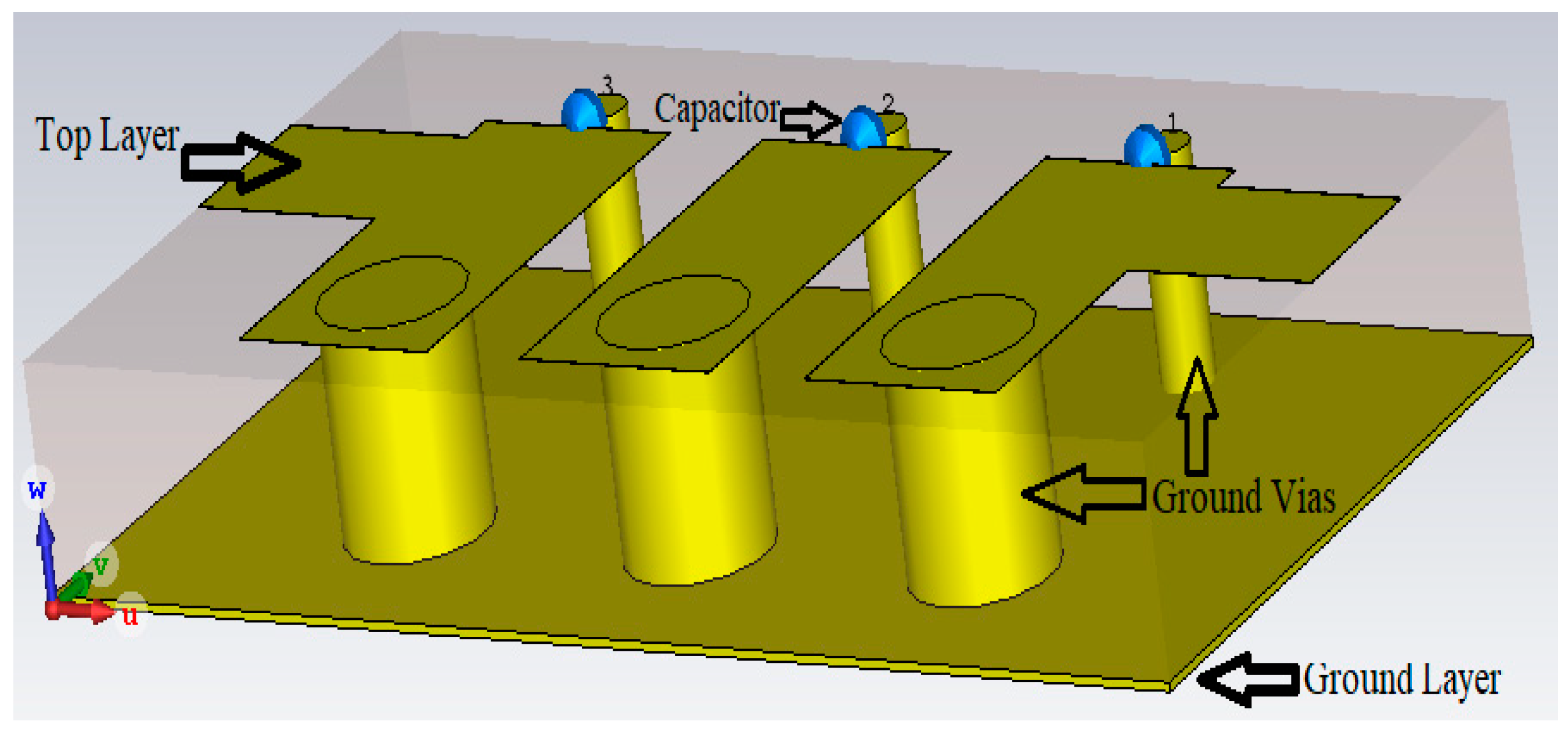
In Reference [38], a compact microstrip band-pass filter (BPF) covering the 3.4–3.8 GHz spectrum bandwidth for 5G wireless communications is presented. The planar filter uses three resonators, each terminated by a via to hole ground at one end and a capacitor at the other end with 50 Ω transmission line impedances for input and output terminals. The coupling between the lines is adjusted to resonate at the centre frequency with third-order band-pass Butterworth properties. The proposed combline filter is designed on an alumina substrate with a relative dielectric constant of 9.8 and a very small size of 9 × 5 × 1.2 mm3. This filter can be easily tuned in frequency by adjusting the capacitors as shown in Figure 1.
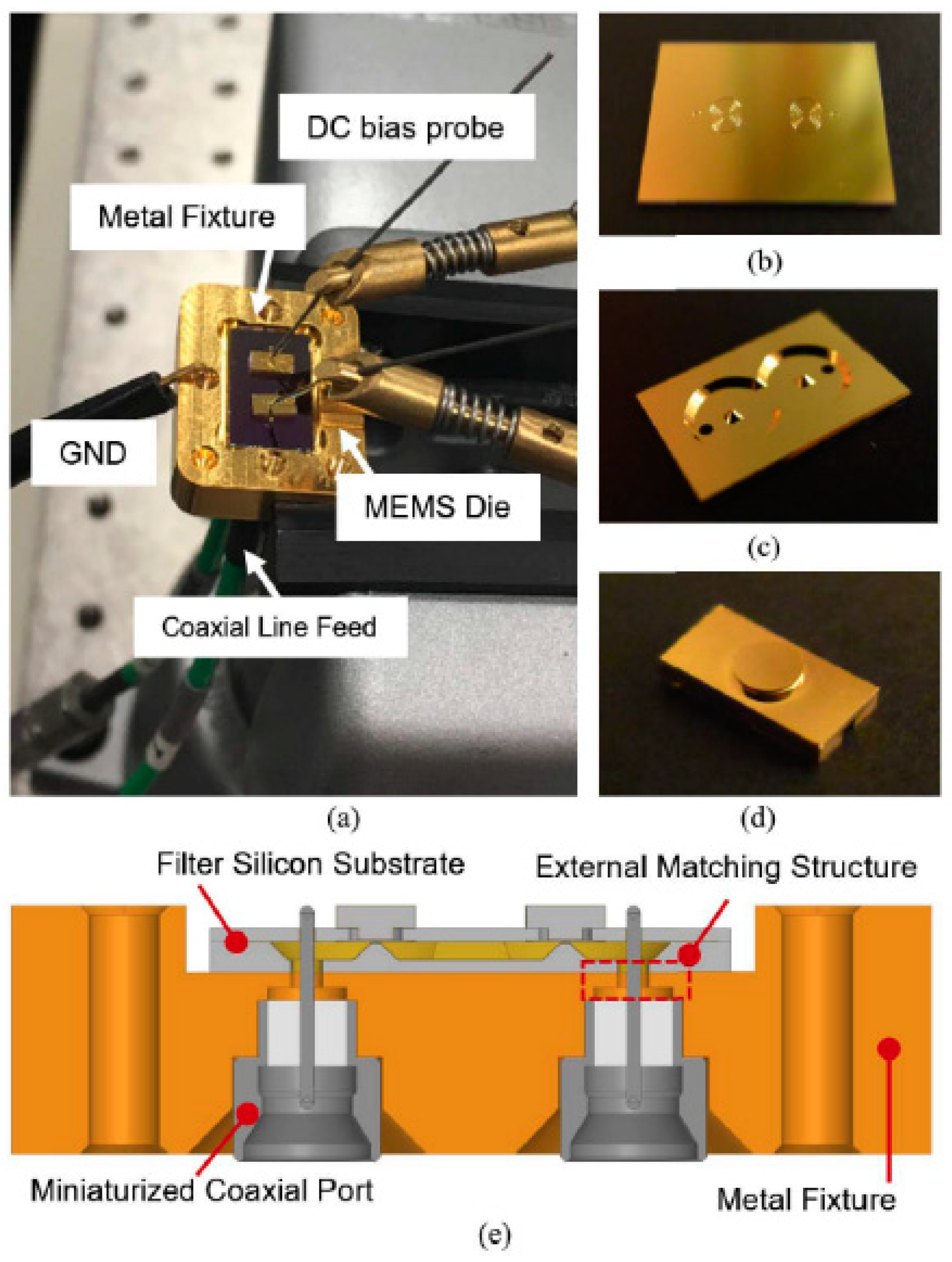
In Reference [39], the authors reported the design and optimization of reconfigurable cavity bandpass filters using MEMS switches with continuously tuneable resonant frequency over a wide tuning band. The tuneable filters are implemented by using silicon micromachining methods, which enables them to be tuned with the desired frequency in the millimetre wave (28–90 GHz) band. Besides, a novel feeding technique is used with fully passive input and output impedance matching over the total tuning range. The filters are tested through electromagnetic software and practically implemented. Figure 2 explains the system installation. An Agilent E836lA network analyser is used to measure the return/insertion loss via a pair of SMA coaxial connectors, which are fixed under the layer of the Au-metallization. The frequency characteristics of the filters are separately adjusted with suitable DC biasing circuits.
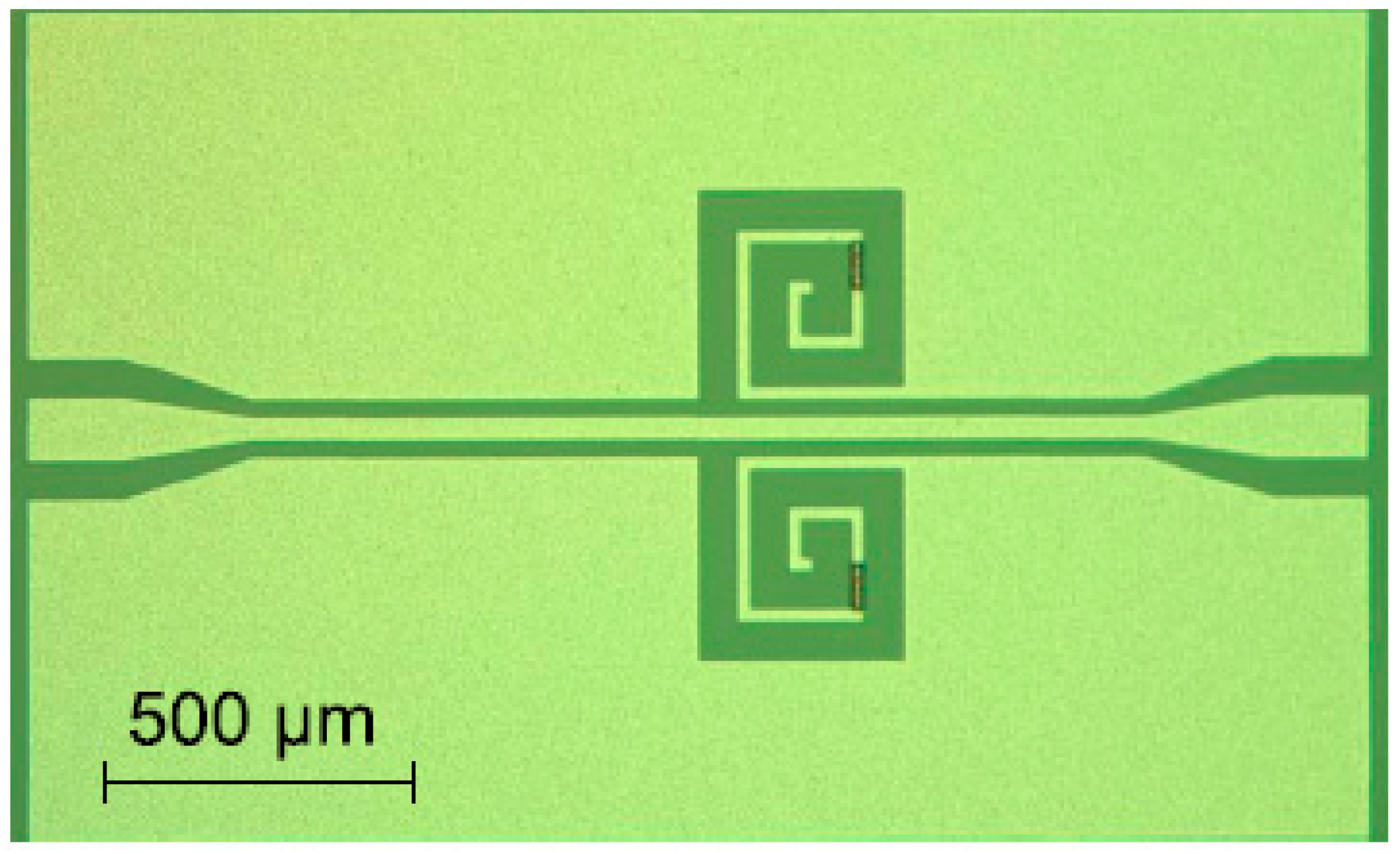
In Reference [40], a novel concept in coplanar waveguide (CPW) reconfigurable band-stop resonator filter was suggested and investigated, with reconfigurability achieved by adjusting the tuning frequency with shortcutting a defected ground (DG) layer. The microstrip reconfigurable filter is implemented based on CMOS techniques with a high resistivity silicon substrate of 300 nm thickness and by exploiting a 1 μm × 10 μm area with a vanadium oxide switch. The tuneable microstrip filter operates in the Ka-band and the reconfigurable resonant frequency covers the mmWave spectrum from 28.2–35 GHz. The paper proposed the use of vanadium oxide in a coplanar waveguide band-stop reconfigurable microstrip filter in the Ka-band. The design was more compact in physical size compared with other coplanar waveguide defected ground reconfigurable filters. The microstrip layer is divided into the amount of the square of the free space wavelength. It is implemented with the highest tuned frequency while showing a reconfigurability of 20%. Figure 3 shows a photo of the filter.
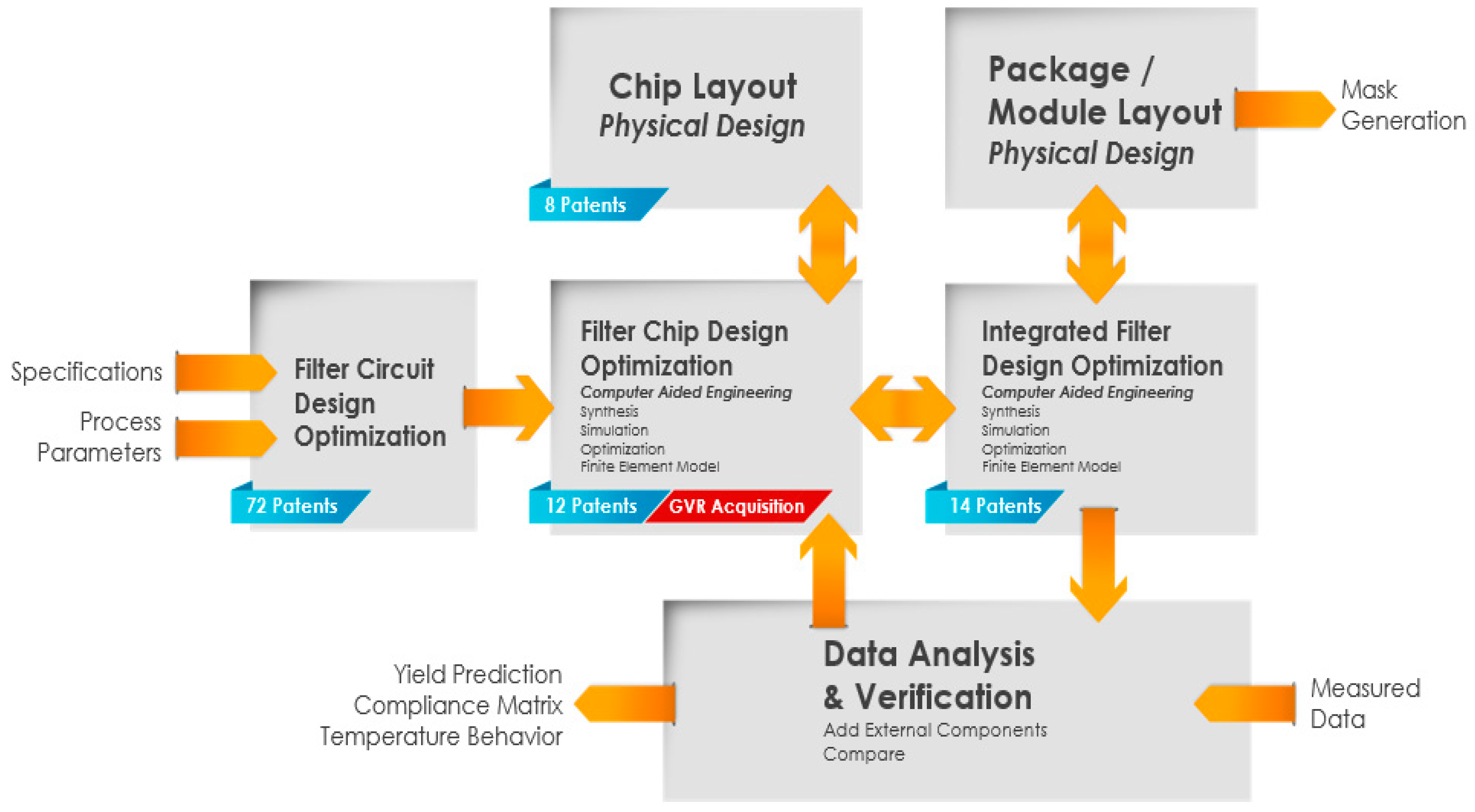
It is noteworthy that a new electronic system developer stage is important to design the compact size, low power handling components that are necessary for fifth generation applications [41] as shown in Figure 4. Recently, many filter companies have established some tools that are not yet developed to get optimal characteristics for filters to be used in 5G applications and there is a challenge to get the optimum designs with the required accuracy while reducing both the cost and time needed. As a result, there is a need for new tools and improvements in current ones to design whole boards and to take into account the following aspects: 1) Modern filter theory. 2) Finite element modelling. 3) New optimization techniques.
4. BAW, SAW and Active Reconfigurable Filters
In this section, we survey and compare reconfigurable surface acoustic wave (SAW), bulk acoustic wave (BAW) and active filters. Firstly, a discussion introduces SAW/BAW reconfigurable filters using varactor diodes integrated with microelectromechanical system (MEMS) technologies and some key techniques that can be employed, showing that high performance can be expected and delivered [42,43,44]. Secondly, active reconfigurable filters based on semiconductor materials and their analysis by hybrid technologies will be discussed [45,46,47].
4.1. BAW and SAW Reconfigurable Filters
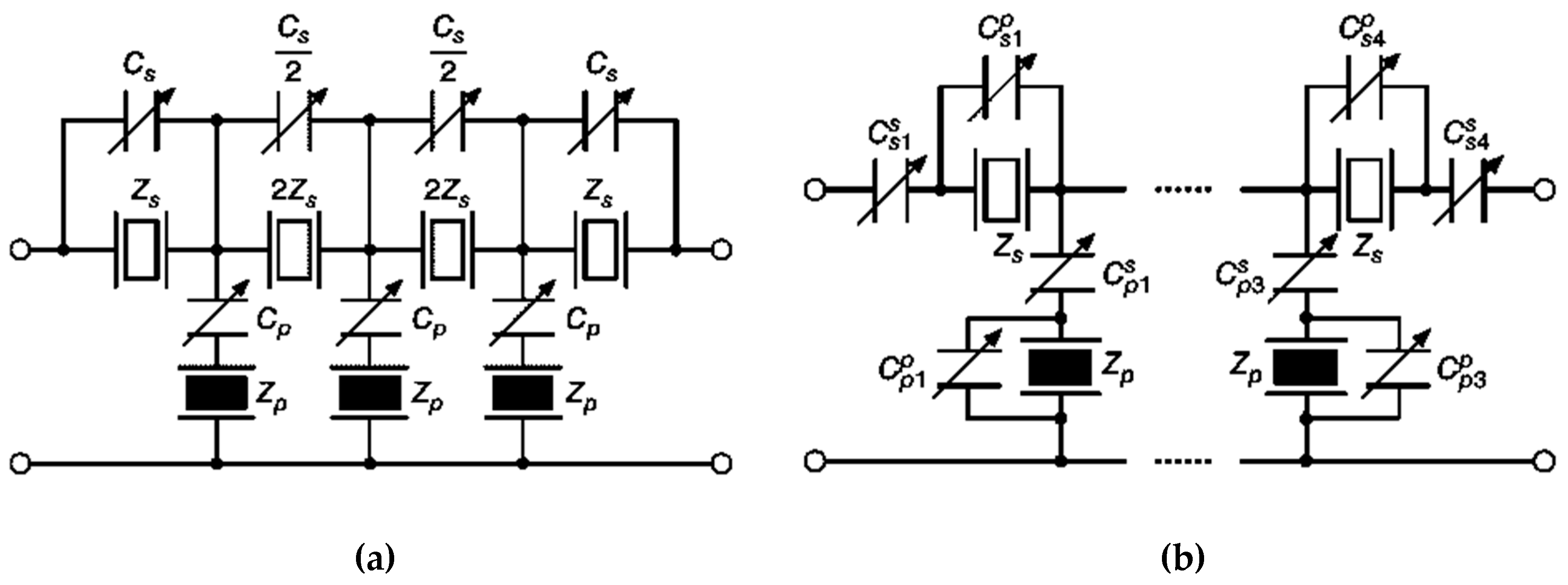
In recent wireless communications, some applications, excluding BPFs with duplexers and power amplifiers, are combined into a single CMOS chip. That is because a high performance is achieved by using SAW/BAW filters for current wireless communication, so providing tuneability without degrading performance is essential. When a very small loss and a very low nonlinearity is preserved and wide range of reconfigurability is realized, reconfigurable SAW/BAW filters can be introduced in various areas. A combination of varactors with wideband SAW filters is presented in Reference [48]. The configurations of this technique are shown in Figure 5a. The advantage of this topology is that the passband characteristic is not sensitive to the quality factors of the varactors but the disadvantage of this approach is the limited reconfigurability due to the availability of a frequency band that is always involved in the passband of the designed filter. With the approach explained in Figure 5b [48], the resonance frequency and the bandwidth of the passband region could be controlled more easily than with previous techniques. The main disadvantage of this topology is the sensitivity of performance of the designed filters to the quality factors of the varactors.
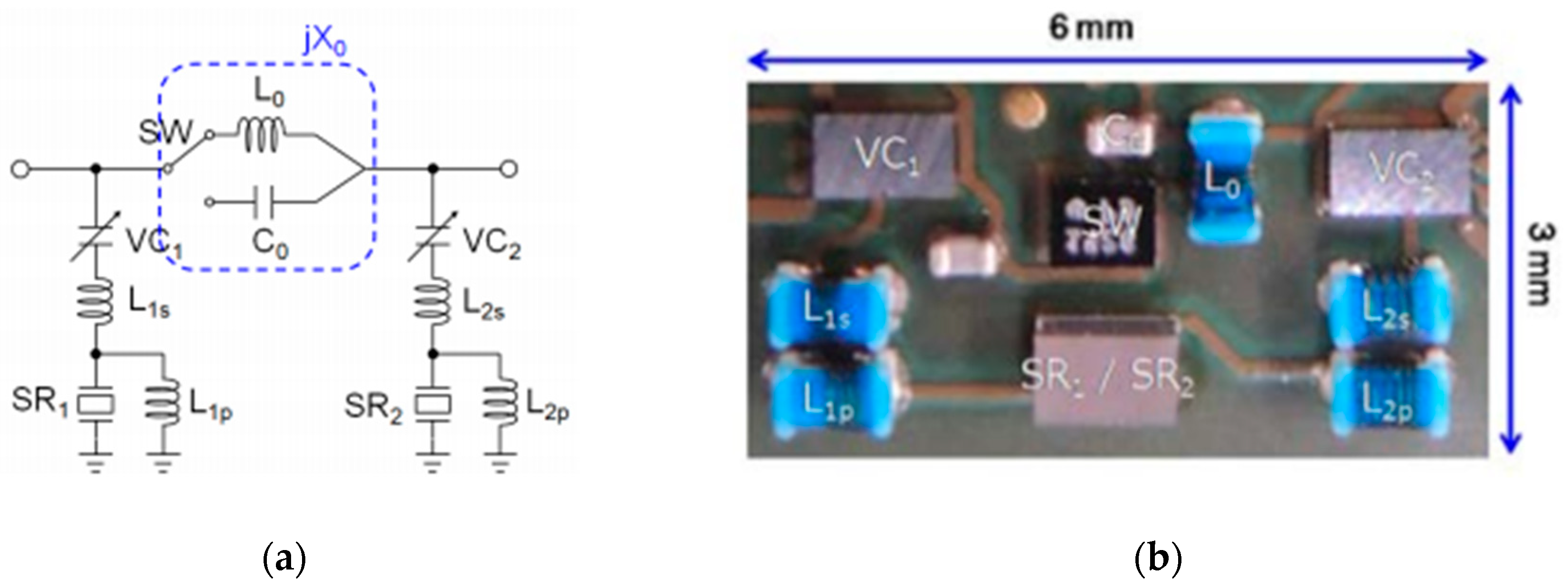
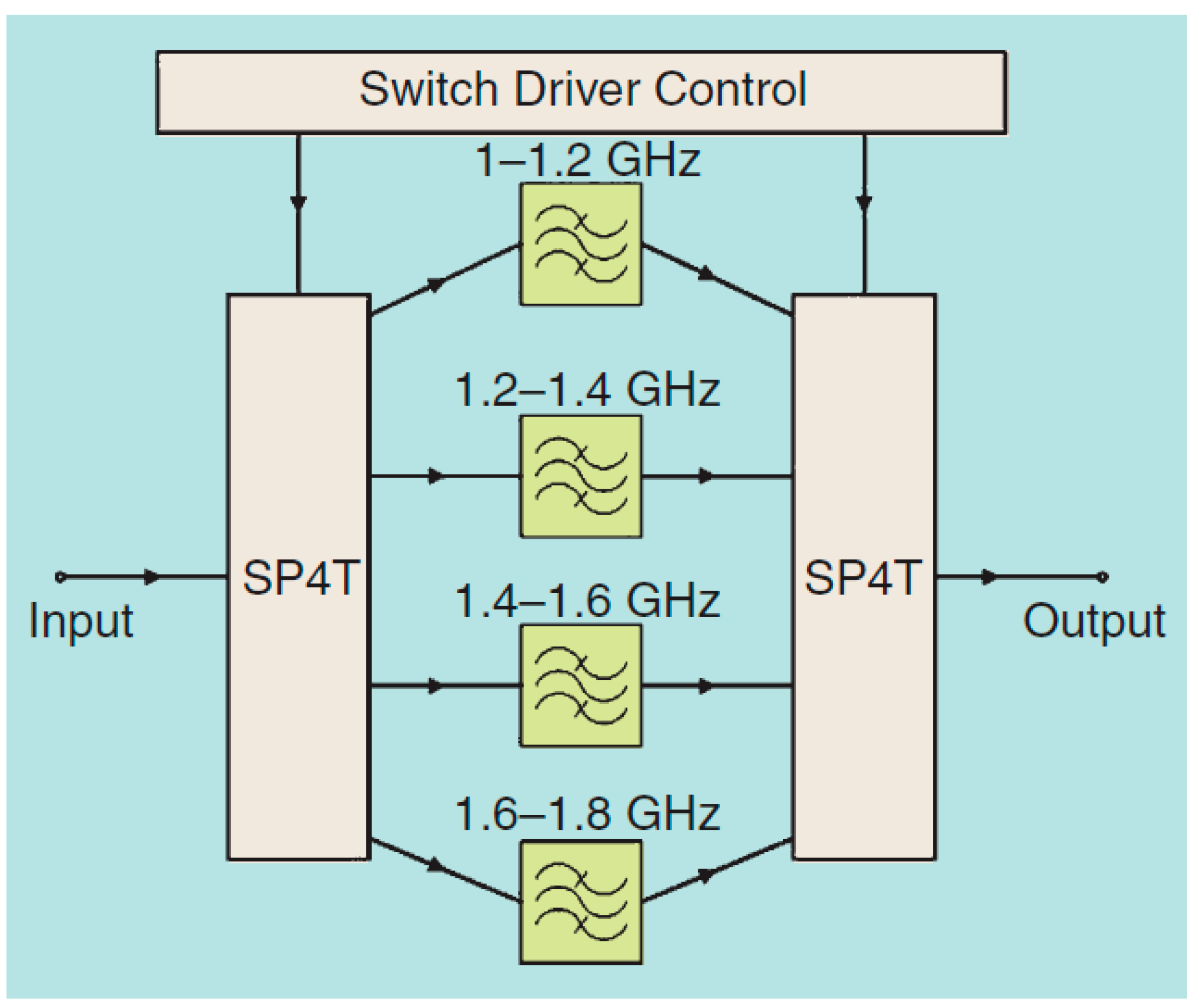
In Reference [49], a novel reconfigurable wideband SAW filter using π type topology is presented for the LTE and UMTS low-band frequency range. Figure 6a shows the configuration of a proposed π type reconfigurable SAW filter circuit. Two reconfigurable filters are connected in parallel with a series arm which includes an inductor L0 and a capacitor C0 selected using a RF switch. Figure 6b shows a top view of the implemented π type reconfigurable filter. Measurements show an isolation value of more than 50 dB with a reconfigurability exceeding 30%.
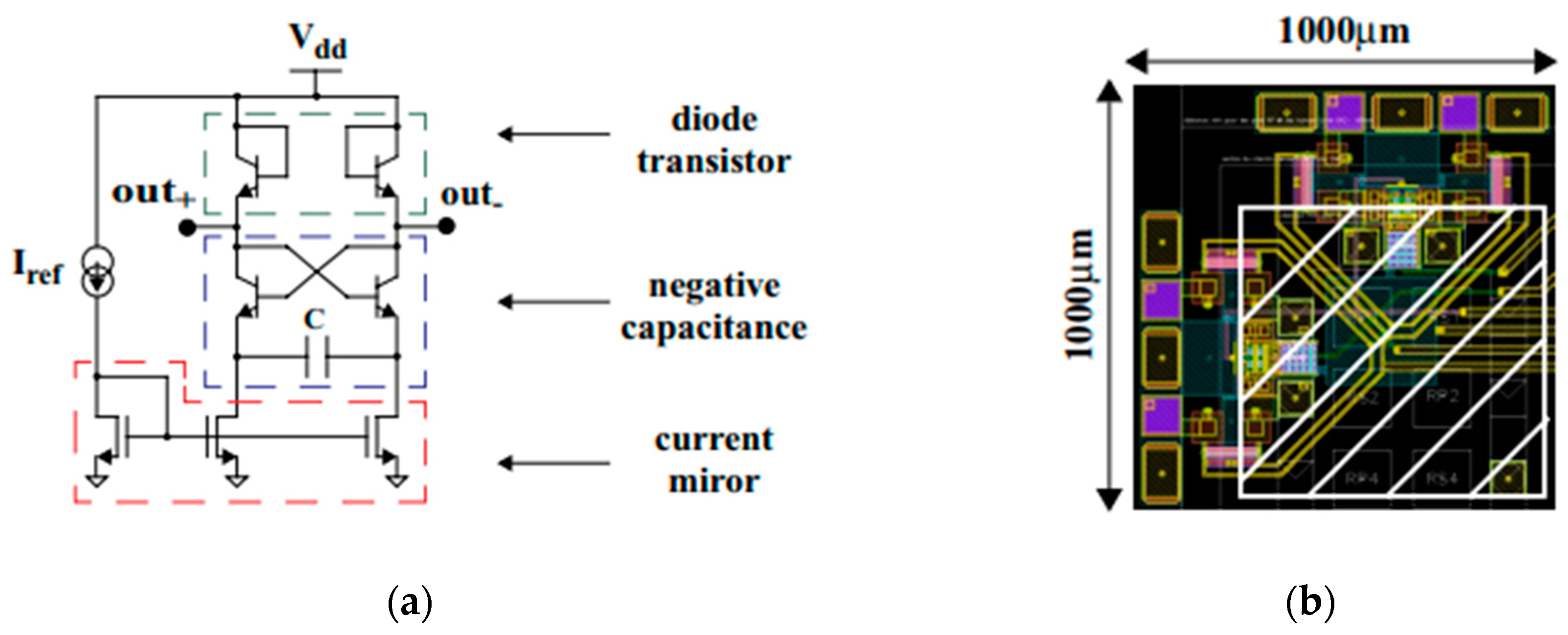
In Reference [50], the authors presented a new reconfigurable BAW filter with negative capacitors. Some similar previous designs were introduced with inductances [51,52]. The disadvantage of these proposed designs is that a second-order parasitic resonant frequency will be generated, leading to a low quality factor of the inductance that reduces the high quality factor of the BAW filter. In Reference [50], the paper presented a solution with a negative capacitance which adjusts the shunt resonance frequency of the BAW filter without generating a parasitic effect. The design includes flip-chip elements of a BAW solidly mounted resonator (SMR) placed on the top of a BiCMOS 0.25 µm chip. Figure 7a shows the configuration of the negative capacitance circuit and the filter layout is depicted in Figure 7b. The designed tunable filter presents a very good level of rejection with less than -50 dB at 1 GHz, improving on previous filters using inductor technologies: the disadvantages of this filter are its power consumption and excess noise.
Generally, both SAW and BAW filters have specific advantages and drawbacks. Mostly, they complement each other. In a few, very limited systems and applications, they compete against each other. As a comparison, BAW tuneable filters have more ability to operate with high frequency bands, high power circuits and high performance compared with SAW tuneable filters.
4.2. Active Reconfigurable Filters
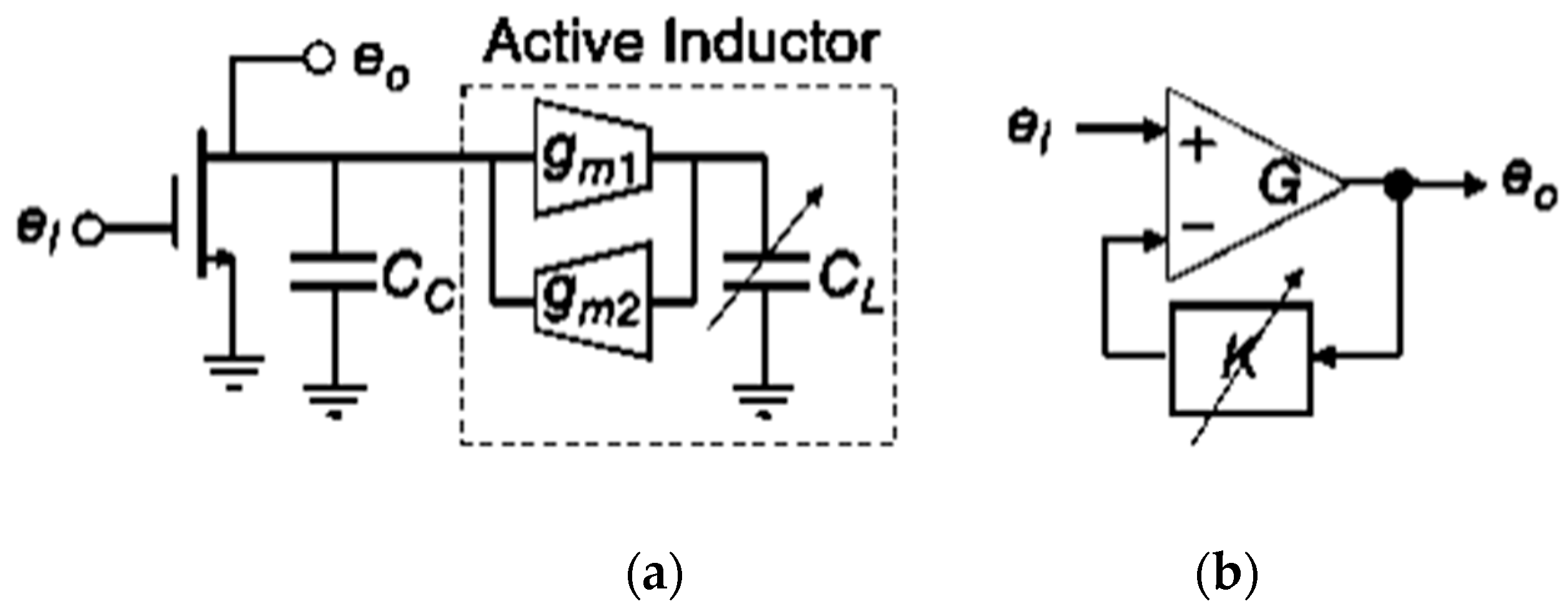
Active tunable filters are also surveyed in this sub-suction. Generally, there are two categories of active tunable filters. Firstly, a resonator tunable filter based on gyrator active inductor [53] as shown in Figure 8a. The design produces a parallel active inductor with Cc and with a voltage gain eo/ei. The centre frequency and the quality factor are adjustable by controlling the values of CL and the transconductance gm, respectively. Secondly, an active filter based a positive feedback loop [45] as shown in Figure 8b. In this filter, the centre frequency and the quality factor are adjustable by varying the values of the phase shift K and the gain G of the amplifier, respectively. These filters can be realized by using the integrated circuits (ICs). The device is consisted of two filter cells coupled in shunt to generate a two pole responses. It should be noted that the centre frequency and the quality factor of each filter cells can be controlled automatically. In these filters, the resonance frequency and the bandwidth can be controlled with a certain renege with a constant filter performance. However, the drawback of these kinds of filters is the nonlinearity.
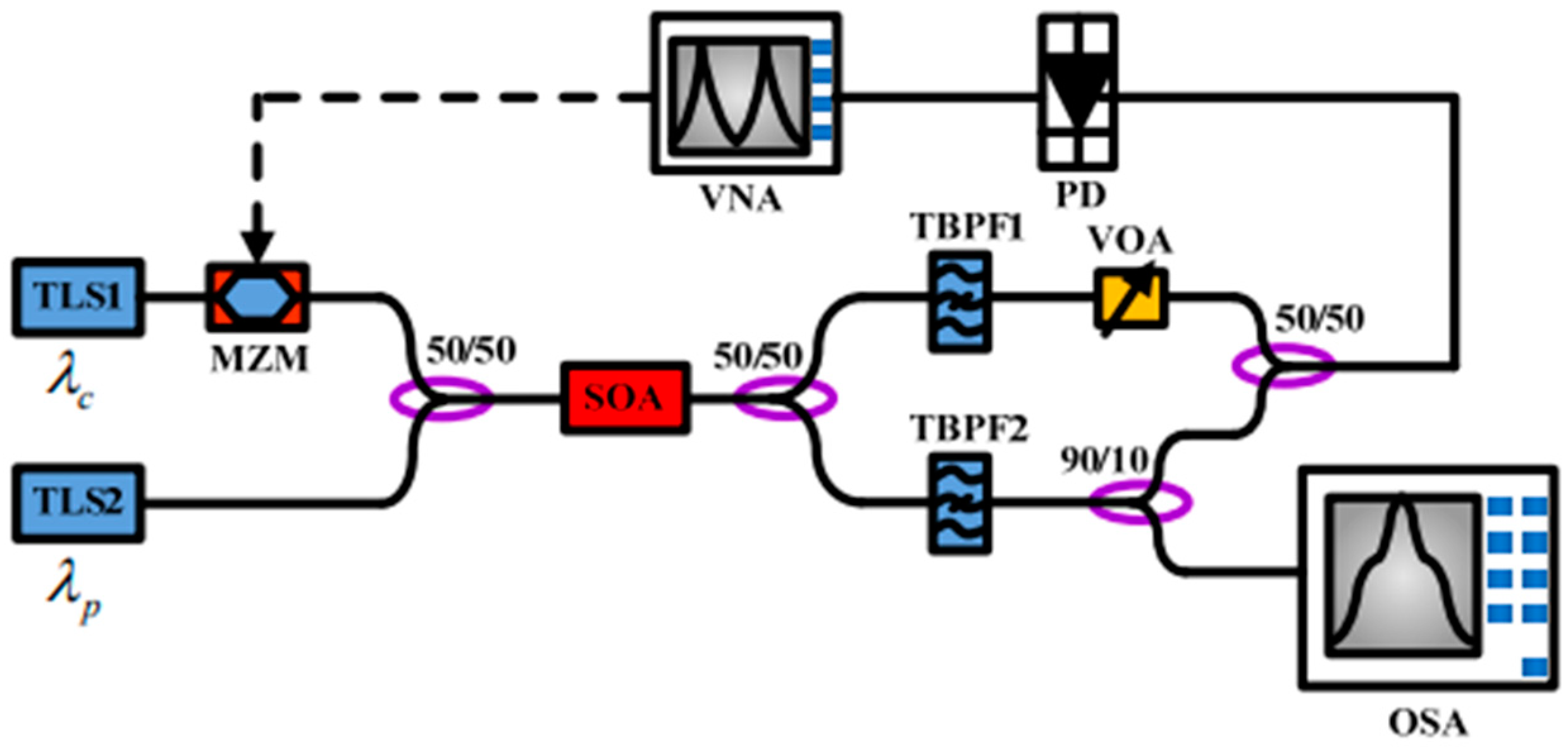
In Reference [54], the paper presented a reconfigurable microwave photonic filter with a wide tuning range, based on a semiconductor optical amplifier. The filter was experimentally implemented and measured with a new configuration, producing a reconfigurable microwave photonic notch filter with a high tuning range about 100%. Figure 9 shows the laboratory measurement set-up. The reconfigurability is realized by controlling the resonance wavelength of the device and the characteristics of the frequency response are fixed throughout the entire tuning mechanism. Additionally, the presented tunable filter has a very compact size, which can be easily combined with the techniques of photonic integrated devices. The filter has a configuration layout similar to that of the filter presented in Reference [55], except that this design incorporates filter detuning.
Another semiconductor-tuned filter by using a cross-phase modulation (XPM) is presented in Reference [56]. The reconfigurability of the proposed filter is realized by varying the fibre delay lines or by dispersive optical fibre. In the designed tunable notch filter, both negative and positive coefficients are achieved by the cross-phase modulation, which leads to a constant frequency response. This scheme prevents further degradation of the system transfer function, unlike the cross-gain modulation (XGM) scheme presented in Reference [57] where only negative coefficients are employed over the amplifier. The XPM configuration also provides a higher RF bandwidth and a lower semiconductor optical amplifier-induced chirp than the XGM configuration in Reference [58].
5. Important Recent Microstrip Tuneable Filter Designs
In this section, we present the most important designs published recently in the microstrip tuneable filter field. Electrically tuneable or reconfigurable RF and microwave resonator filters are increasingly attractive to researchers and developers of RF and microwave circuit, because this technique is necessary to achieve compact and profitable electronic systems for future generations of wireless communication applications. These filters have different applications in wireless communication systems, such as in mixers and receiver preselection. To include electrical reconfigurability in resonator filters, reconfiguration components and switching elements like RF MEMS, semiconductor diodes, transistors and optical switches are used as shown in Figure 10 [59,60].
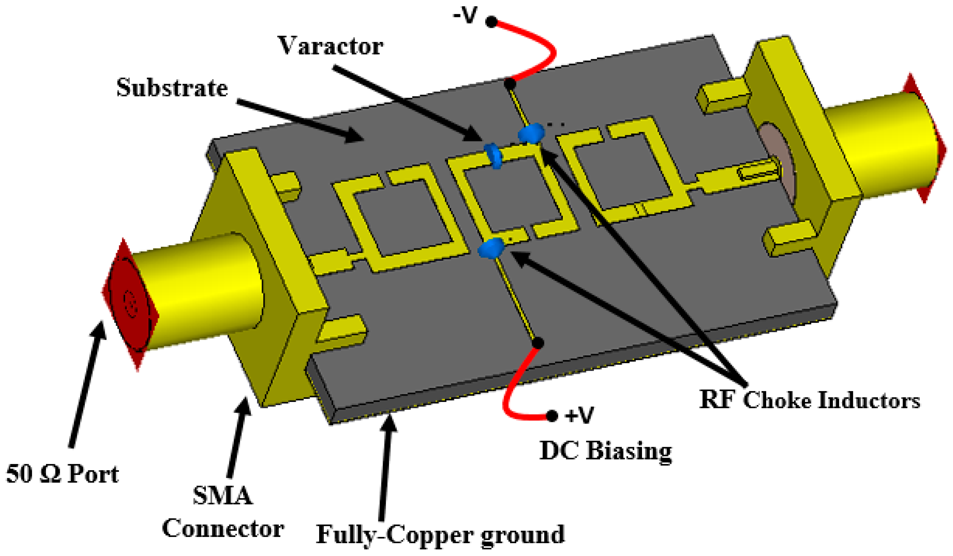
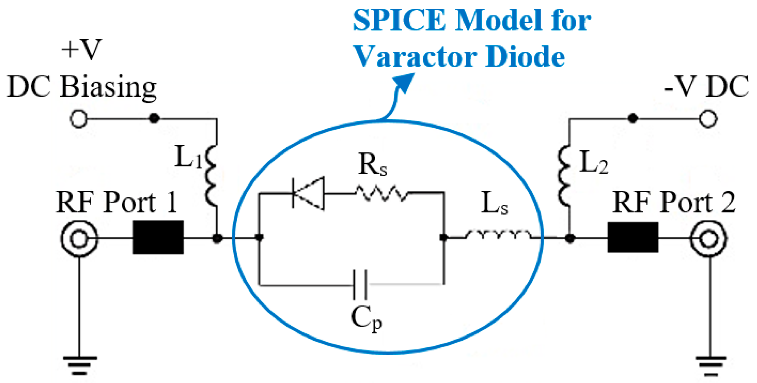
A design for a compact 5G reconfigurable-microstrip bandpass filter with third-order and Butterworth filter properties is presented in Reference [61]. The filter is reconfigurable in both resonant frequency and bandwidth to cover 3.4–3.8 GHz under the control of a single varactor diode switch. The design exhibits a 50–130 MHz bandwidth with return loss between 20–37 dB and insertion loss around 1 dB. The filter covers the 5G frequency spectrum for possible use in stationary terminals of both wireless communication and cognitive radio systems. Figure 11 shows a 3D structure of the filter. The biasing circuit, with the SPICE model for the varactor, is modelled as shown in Figure 12. For implementation, Skyworks Solutions SMV1234, size 1.5 × 0.7 mm2, is used as the varactor switch.
Another novel tuneable low-pass filter (LPF) using varactor diodes with high selectivity within the tuning range and wide stopband has been reported in Reference [62]. Stepped impedance resonators (SIR) and low impedance stubs of stepped-impedance resonators are used to achieve a tuneable resonator filter by means of varactor switches arranged in parallel and reconfigurable coupling lines arranged in series.
Two semi-circular slots are adopted in the ground layer, while the microstrip layers have been connected with feed lines at both terminals to achieve a wide stopband for the filter. A stopband is maintained up to 22 GHz for the lower frequency with a rejection level of less than 10 dB. The presented tuneable microstrip filter has a very good performance compared with other LPF filter designs. Figure 13 shows the structure of the tuneable microstrip LPF.
Modern wireless communication applications usually work with multi-bands. A novel structure of the miniaturized ring resonator tuneable filter is proposed in Reference [63]. The filter is designed with a single element, multi-mode, adjustable line impedance and microstrip material. The bandwidth of the resonator is enhanced significantly to include the entire range of the ultra-wideband (UWB) frequency with a wide area of reconfigurability. The filter has a high stopband and good performance. As long as the design of the filter is symmetrical, even and odd modes analysis have been used to study the required performance for the structure. The filter can be adapted to fulfil the required characteristics for various wireless applications. In addition, PIN diodes and varactor switches are used to achieve a high-level capacity for tunability with different performances are achieved for bandwidths, resonant frequencies and stopband frequencies. Figure 14 shows a photograph of the filter [63].
Another interesting design is introduced in Reference [64] to operate with a wideband covering the frequency range 3.5–10 GHz. Most referenced works in this paper were analogue and digital MEMS resonator filters. Open-stub ring resonators and advanced microelectromechanical system (MEMS) switches were used, giving high selectivity for the passband and adjusted DC biasing voltage up to 25 V.
A hybrid tuneable structure employing both series and shunt resonators is employed to achieve the desired characteristics. The switches are used for the biasing circuit to drive the required voltage levels. The design delivers the exact expected performance with the aid of the equivalent transmission line circuit of the microstrip filter. Compared with the PIN diode tuneable filters in Reference [65,66,67,68], the MEMS tuneable filter has a high quality factor and a good rejection in the stopband. Figure 15 shows the design with the installed layout.
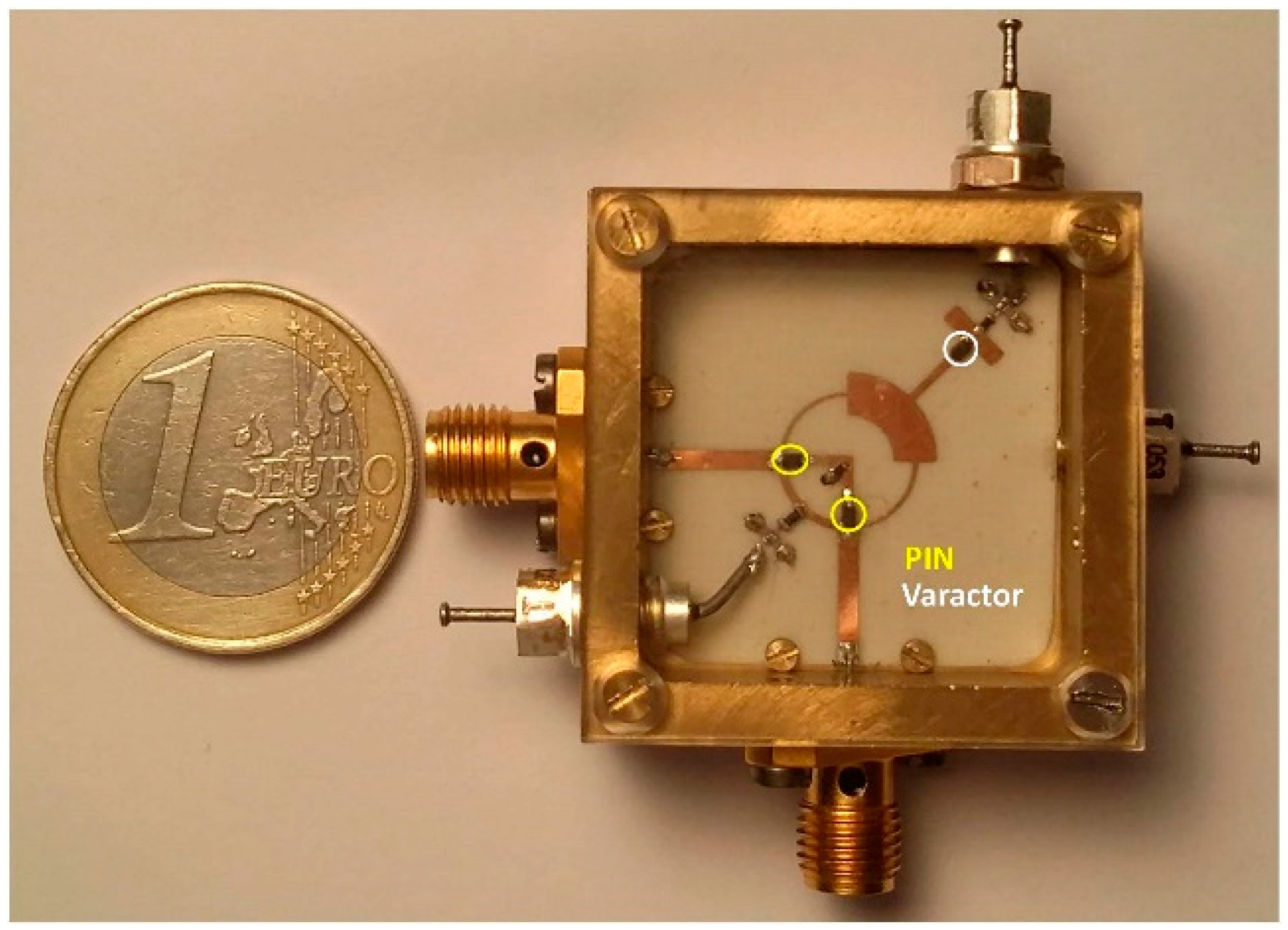
A multi-band reconfigurable filter is proposed in Reference [69]. The filter has a tunable resonance frequency and selection of bandpass and band-stop characteristics by using a PIN diode switch. Two varactor diodes are used at the input and output of the transmission lines to adjust the quality factor. The centre frequency can be tuned continuously from 1.6–2.6 GHz during the bandpass configuration or from 1.6–3 GHz during the stopband configuration. The insertion loss in the bandpass configuration is adjusted by controlling the biasing voltage across the varactor diode, taking into account the loss of the PIN switch [70]. Figure 16 shows the filter.
Table 1 Summarises performance comparisons for main recent and important references in the literature with the scope of microstrip reconfigurable filters.
Varactor and PIN diodes are used as switches for all these designs. Low-pass filter (LPF), bandpass filter (BPF) and band-stop filter (BSF) are detailed in this comparison with different kinds of reconfiguration such as frequency, bandwidth and selectivity reconfigurations. The number of switches, filter size with resulted return loss (RL) and insertion loss (IL) are also summarized in this table, giving readers and researchers a general overview of the latest designs and achievements in the field of microstrip tuneable filters.
6. Conclusions
In this paper, a brief overview in the development of RF microwave tuneable filter is presented. During more than a decade of wide research, there has been a tremendous improvement in the design and implementation of reconfigurable filters and their applications in the RF microwave field. The paper reviews recent designs of microwave tuneable filter topology and it gives the general background to the important source materials needed by researchers in the field of tuneable filter technology. It reviews recent developments in the field of tuneable RF, microwave and mmWave filters. Reconfigurable filters for the next generation of wireless communication applications are surveyed, with a selection from the most important recently published articles. The main recent design references are summarised with performance comparisons of achievements in this field.
Author Contributions
Conceptualization, Y.I.A.A.-Y.; methodology, Y.I.A.A.-Y. and N.O.P.; investigation, Y.I.A.A.-Y., A.M.A. and R.A.A.-A.; resources, Y.I.A.A.-Y., N.O.P, A.M.A. and R.A.A.-A.; writing—original draft preparation, Y.I.A.A.-Y., N.O.P., A.M.A., R.A.A.-A. and J.M.N.; writing—review and editing, Y.I.A.A.-Y., A.M.A., R.A.A.-A. and J.M.N.; visualization, Y.I.A.A.-Y., A.M.A., R.A.A.-A. and J.M.N.
Funding
This project has received funding from the European Union’s Horizon 2020 research and innovation programme under grant agreement H2020-MSCA-ITN-2016 SECRET-722424.
Acknowledgments
This project has received funding from the European Union’s Horizon 2020 research and innovation programme under grant agreement H2020-MSCA-ITN-2016 SECRET-722424.
Conflicts of Interest
The authors declare no conflict of interest.
References
- Hunter, I. Theory and Design of Microwave Filters; The Institution of Engineering and Technology: Stevenage, UK, 2001. [Google Scholar] [CrossRef]
- Hong, J.-S.; Lancaster, M.J. Microstrip Filters for RF/Microwave; John Wiley and Sons: Hoboken, NJ, USA, 2004; Volume 167. [Google Scholar]
- Cameron, R.J.; Kudsia, C.M.; Mansour, R.R. Microwave Filters for Communication Systems: Fundamentals, Design and Applications, 2nd ed.; Wiley: Hoboken, NJ, USA, 2018. [Google Scholar]
- Hunter, I.C.; Rhodes, J.D. Electronically Tuneable Microwave Bandpass Filters. IEEE Trans. Microw. Theory Tech. 1982, 30, 1354–1360. [Google Scholar] [CrossRef]
- Byung-Wook, K.; Sang-Won, Y. Varactor-tuned combline bandpass filter using step-impedance microstrip lines. IEEE Trans. Microw. Theory Tech. 2004, 52, 1279–1283. [Google Scholar] [CrossRef]
- Sanchez-Renedo, M.; Gomez-Garcia, R.; Alonso, J.I.; Briso-Rodriguez, C. Tuneable combline filter with continuous control of center frequency and bandwidth. IEEE Trans. Microw. Theory Tech. 2005, 53, 191–199. [Google Scholar] [CrossRef]
- Wang, X.; Cho, Y.; Yun, S. A Tuneable Combline Bandpass Filter Loaded With Series Resonator. IEEE Trans. Microw. Theory Tech. 2012, 60, 1569–1576. [Google Scholar] [CrossRef]
- Park, S.; Rebeiz, G.M. Low-Loss Two-Pole Tuneable Filters With Three Different Predefined Bandwidth Characteristics. IEEE Trans. Microw. Theory Tech. 2008, 56, 1137–1148. [Google Scholar] [CrossRef]
- Zhang, X.Y.; Xue, Q.; Chan, C.H.; Hu, B. Low-Loss Frequency-Agile Bandpass Filters With Controllable Bandwidth and Suppressed Second Harmonic. IEEE Trans. Microw. Theory Tech. 2010, 58, 1557–1564. [Google Scholar] [CrossRef]
- El-Tanani, M.A.; Rebeiz, G.M. Corrugated Microstrip Coupled Lines for Constant Absolute Bandwidth Tuneable Filters. IEEE Trans. Microw. Theory Tech. 2010, 58, 956–963. [Google Scholar] [CrossRef]
- Tang, W.; Hong, J. Varactor-Tuned Dual-Mode Bandpass Filters. IEEE Trans. Microw. Theory Tech. 2010, 58, 2213–2219. [Google Scholar] [CrossRef]
- Tsai, H.; Chen, N.; Jeng, S. Center Frequency and Bandwidth Controllable Microstrip Bandpass Filter Design Using Loop-Shaped Dual-Mode Resonator. IEEE Trans. Microw. Theory Tech. 2013, 61, 3590–3600. [Google Scholar] [CrossRef]
- Serrano, A.L.C.; Correra, F.S.; Vuong, T.; Ferrari, P. Synthesis Methodology Applied to a Tuneable Patch Filter With Independent Frequency and Bandwidth Control. IEEE Trans. Microw. Theory Tech. 2012, 60, 484–493. [Google Scholar] [CrossRef]
- Xiang, Q.; Feng, Q.; Huang, X.; Jia, D. Electrical Tuneable Microstrip LC Bandpass Filters With Constant Bandwidth. IEEE Trans. Microw. Theory Tech. 2013, 61, 1124–1130. [Google Scholar] [CrossRef]
- Chiou, Y.; Rebeiz, G.M. A Tuneable Three-Pole 1.5–2.2-GHz Bandpass Filter With Bandwidth and Transmission Zero Control. IEEE Trans. Microw. Theory Tech. 2011, 59, 2872–2878. [Google Scholar] [CrossRef]
- Chiou, Y.; Rebeiz, G.M. A Quasi Elliptic Function 1.75–2.25 GHz 3-Pole Bandpass Filter With Bandwidth Control. IEEE Trans. Microw. Theory Tech. 2012, 60, 244–249. [Google Scholar] [CrossRef]
- Chiou, Y.; Rebeiz, G.M. Tuneable 1.55-2.1 GHz 4-Pole Elliptic Bandpass Filter With Bandwidth Control and >50 dB Rejection for Wireless Systems. IEEE Trans. Microw. Theory Tech. 2013, 61, 117–124. [Google Scholar] [CrossRef]
- Carey-Smith, B.E.; Warr, P.A. Distortion Mechanisms in Varactor Diode-Tuned Microwave Filters. IEEE Trans. Microw. Theory Tech. 2006, 54, 3492–3500. [Google Scholar] [CrossRef] [Green Version]
- El-Tanani, M.A.; Rebeiz, G.M. A Two-Pole Two-Zero Tuneable Filter With Improved Linearity. IEEE Trans. Microw. Theory Tech. 2009, 57, 830–839. [Google Scholar] [CrossRef]
- Athukorala, L.; Budimir, D. Compact Second-Order Highly Linear Varactor-Tuned Dual-Mode Filters With Constant Bandwidth. IEEE Trans. Microw. Theory Tech. 2011, 59, 2214–2220. [Google Scholar] [CrossRef]
- Ou, Y.; Rebeiz, G.M. Lumped-Element Fully Tuneable Band-stop Filters for Cognitive Radio Applications. IEEE Trans. Microw. Theory Tech. 2011, 59, 2461–2468. [Google Scholar] [CrossRef]
- Zhang, X.Y.; Chan, C.H.; Xue, Q.; Hu, B. RF Tuneable Band-stop Filters With Constant Bandwidth Based on a Doublet Configuration. IEEE Trans. Ind. Electron. 2012, 59, 1257–1265. [Google Scholar] [CrossRef]
- Wang, X.; Wang, B.; Zhang, H.; Chen, K.J. A Tuneable Band-stop Resonator Based on a Compact Slotted Ground Structure. IEEE Trans. Microw. Theory Tech. 2007, 55, 1912–1918. [Google Scholar] [CrossRef]
- Wang, Z.P.; Kelly, J.; Hall, P.S. Reconfigurable band-stop filter with wide tuning range. Electron. Lett. 2010, 46, 771–772. [Google Scholar] [CrossRef]
- Guyette, A.C. Design of fixed- and varactor-tuned band-stop filters with spurious suppression. In Proceedings of the 40th European Microwave Conference, Paris, France, 28–30 September 2010; pp. 288–291. [Google Scholar]
- Huang, C.; Chen, N.; Tsai, H.; Chen, J. A coplanar waveguide bandwidth-tuneable low-pass filter with broadband rejection. IEEE Microw. Wirel. Compon. Lett. 2013, 23, 134–136. [Google Scholar] [CrossRef]
- Abbosh, A. Compact tuneable low-pass filter using variable mode impedance of coupled structure. IET Microw. Antennas Propag. 2012, 6, 1306–1310. [Google Scholar] [CrossRef]
- Levy, R.; Cohn, S.B. A History of Microwave Filter Research, Design and Development. IEEE Trans. Microw. Theory Tech. 1984, 32, 1055–1067. [Google Scholar] [CrossRef]
- Levy, R.; Snyder, R.V.; Matthaei, G. Design of microwave filters. IEEE Trans. Microw. Theory Tech. 2002, 50, 783–793. [Google Scholar] [CrossRef]
- Hunter, I.C.; Billonet, L.; Jarry, B.; Guillon, P. Microwave filters-applications and technology. IEEE Trans. Microw. Theory Tech. 2002, 50, 794–805. [Google Scholar] [CrossRef]
- Hussaini, A.; Al-Yasir, Y.I.A.; Voudouris, K.; Mohammed, B.; Abd-Alhameed, R.; Mohammed, H.; Elfergani, I.; Abdullah, A.; Makris, D.; Rodriguez, J.; et al. Green Flexible RF for 5G. In Fundamentals of 5G Mobile Networks, 1st ed.; Rodriguez, J., Ed.; John Wiley and Sons: Hoboken, NJ, USA, 2015. [Google Scholar]
- Al-Yasir, Y.I.A.; Abdullah, A.; Mohammed, H.; Mohammedand, B.; Abd-Alhameed, R. Design of Radiation Pattern-Reconfigurable 60-GHz Antenna for 5G Applications. J. Telecommun. 2014, 27, 1–6. [Google Scholar]
- Abdulraheem, Y.I.; Oguntala, G.A.; Abdullah, A.S.; Mohammed, H.J.; Ali, R.A.; Abd-Alhameed, R.A.; Noras, J.M. Design of frequency reconfigurable multiband compact antenna using two PIN diodes for WLAN/WiMAX applications. IET Microw. Antennas Propag. 2017, 11, 1098–1105. [Google Scholar] [CrossRef]
- Al-Yasir, Y.; Abdullah, A.; Ojaroudi Parchin, N.; Abd-Alhameed, R.; Noras, J. A New Polarization-Reconfigurable Antenna for 5G Applications. Electronics 2018, 7, 293. [Google Scholar] [CrossRef]
- Statement: Improving consumer access to mobile services at 3.6 GHz to 3.8 GHz. Available online: https://www.ofcom.org.uk/consultations-and-statements/category-1/future-use-at-3.6-3.8-ghz (accessed on 28 July 2017).
- Jeon, J.S.; Kang, S.T.; Kim, H.S. GA-optimized compact broadband CRLH band-pass filter using stub-inserted interdigital coupled lines. J. Electromagn. Eng. Sci. 2015, 15, 31–36. [Google Scholar] [CrossRef]
- Wang, C.; Haider, F.; Gao, X.; You, X.; Yang, Y.; Yuan, D.; Aggoune, H.M.; Haas, H.; Fletcher, S.; Hepsaydir, E. Cellular architecture and key technologies for 5G wireless communication networks. IEEE Commun. Mag. 2014, 52, 122–130. [Google Scholar] [CrossRef] [Green Version]
- Al-Yasir, Y.; Abd-Alhameed, R.A.; Noras, J.M.; Abdulkhaleq, A.M.; Ojaroudi, N. Design of Very Compact Combline Band-Pass Filter for 5G Applications. In Proceedings of the 2018 Loughborough Antennas & Propagation Conference (LAPC), Loughborough, UK, 12–13 November 2018; pp. 1–4. [Google Scholar]
- Yang, Z.; Psychogiou, D.; Peroulis, D. Design and Optimization of Tuneable Silicon-Integrated Evanescent-Mode Bandpass Filters. IEEE Trans. Microw. Theory Tech. 2018, 66, 1790–1803. [Google Scholar] [CrossRef]
- Casu, E.A.; Müller, A.A.; Fernández-Bolaños, M.; Fumarola, A.; Krammer, A.; Schüler, A.; Ionescu, A.M. Vanadium Oxide Band-stop Tuneable Filter for Ka Frequency Bands Based on a Novel Reconfigurable Spiral Shape Defected Ground Plane CPW. IEEE Access 2018, 6, 12206–12212. [Google Scholar] [CrossRef]
- Infinite Synthesized Networks. Available online: https://www.resonant.com/technology/infinite-synthesized-networks (accessed on 8 February 2012).
- Weigel, R.; Morgan, D.P.; Owens, J.M.; Ballato, A.; Lakin, K.M.; Hashimoto, K.; Ruppel, C.C.W. Microwave acoustic materials, devices and applications. IEEE Trans. Microw. Theory Tech. 2002, 50, 738–749. [Google Scholar] [CrossRef]
- Tokihiro, N.; Masafumi, I.; Go, E.; Xiaoyu, M.; Shinji, T.; Masanori, U.; Yoshio, S. BAW/SAW/IPD hybrid type duplexer with Rx balanced output for WCDMA Band I. In Proceedings of the 2008 IEEE MTT-S International Microwave Symposium Digest, Atlanta, GA, USA, 15–20 June 2008; pp. 831–834. [Google Scholar]
- Yang, J.; Jiao, X.; Zhang, R.; Zhong, H.; Shi, Y. Fabrication of bulk acoustic wave resonator based on AlN thin film. In Proceedings of the 2012 Symposium on Piezoelectricity, Acoustic Waves and Device Applications (SPAWDA), Shanghai, China, 23–25 November 2012; pp. 191–194. [Google Scholar]
- Omori, T.; Seo, K.; Ahn, T.F.C.; Hashimoto, K. Flexible RF one-chip active filter based on recursive architecture in UHF range. In Proceedings of the 2014 Asia-Pacific Microwave Conference, Sendai, Japan, 4–7 November 2014; pp. 1309–1311. [Google Scholar]
- Darfeuille, S.; Gomez-Garcia, R.; Lintignat, J.; Sassi, Z.; Barelaud, B.; Billonnet, L.; Jarry, B.; Marie, H.; Gamand, P. Silicon-Integrated 2-GHz Fully-Differential Tunable Recursive Filter for MMIC Three-Branch Channelized Bandpass Filter Design. In Proceedings of the 2006 IEEE MTT-S International Microwave Symposium Digest, San Francisco, CA, USA, 11–16 June 2006; pp. 776–779. [Google Scholar]
- Omori, T.; Nishiuma, S.; Seo, K.; Ahn, C.; Hashimoto, K.; Kamada, M. Integrated RF tunable filter based on recursive architecture and its application. In Proceedings of the 2013 European Microwave Integrated Circuit Conference, Nuremberg, Germany, 6–8 October 2013; pp. 548–551. [Google Scholar]
- Tomoya, K.; Ken-ya, H.; Tatsuya, O.; Masatsune, Y. Tunable Radio-Frequency Filters Using Acoustic Wave Resonators and Variable Capacitors. Jpn. J. Appl. Phys. 2010, 49, 07HD24. [Google Scholar]
- Wada, T.; Ogami, T.; Horita, A.; Obiya, H.; Koshino, M.; Kawashima, M.; Nakajima, N. A new tunable SAW filter circuit for reconfigurable RF. In Proceedings of the 2016 IEEE MTT-S International Microwave Symposium (IMS), San Francisco, CA, USA, 22–27 May 2016; pp. 1–4. [Google Scholar]
- Tilhac, C.; Razafimandimby, S.; Cathelin, A.; Bila, S.; Madrangeas, V.; Belot, D. A tunable bandpass BAW-filter architecture using negative capacitance circuitry. In Proceedings of the 2008 IEEE Radio Frequency Integrated Circuits Symposium, Atlanta, GA, USA, 15–17 June 2008; pp. 605–608. [Google Scholar]
- Razafimandimby, S.; Tilhac, C.; Cathelin, A.; Kaiser, A.; Belot, D. A novel architecture of a tunable bandpass BAW-filter for a WCDMA transceiver. Analog Integr. Circuits Signal Process. 2006, 49, 237–247. [Google Scholar] [CrossRef]
- Razafimandimby, S.; Tilhac, C.; Cathelin, A.; Kaiser, A.; Belot, D. An Electronically Tunable Bandpass BAW-Filter for a Zero-IF WCDMA Receiver. In Proceedings of the 32nd European Solid-State Circuits Conference, Montreux, Switzerland, 19–21 September 2006; pp. 142–145. [Google Scholar]
- Haiqiao, X.; Schaumann, R.; Daasch, W.R.; Wong, P.K.; Pejcinovic, B. A radio-frequency CMOS active inductor and its application in designing high-Q filters. In Proceedings of the 2004 IEEE International Symposium on Circuits and Systems (IEEE Cat. No.04CH37512), Vancouver, BC, Canada, 23–26 May 2004; p. IV-197. [Google Scholar]
- Li, X.; Yu, Y.; Dong, J.; Zhang, X. Widely tunable microwave photonic filter based on semiconductor optical amplifier. In Proceedings of the Asia Communications and Photonics Conference and Exhibition, Shanghai, China, 8–12 December 2010; pp. 122–123. [Google Scholar]
- Coppinger, F.; Yegnanarayanan, S.; Trinh, P.D.; Jalali, B. All-optical RF filter using amplitude inversion in a semiconductor optical amplifier. IEEE Trans. Microw. Theory Tech. 1997, 45, 1473–1477. [Google Scholar] [CrossRef] [Green Version]
- Manzanedo, M.D.; Mora, J.; Ortega, B.; Capmany, J. Tunable all-optical microwave filter using Cross-Phase Modulation in Semiconductor Optical Amplifier Mach-Zehnder interferometer. In Proceedings of the 2006 International Topical Meeting on Microwave Photonics, Grenoble, France, 3–6 October 2006; pp. 1–4. [Google Scholar]
- Mora, J.; Martinez, A.; Manzanedo, M.D.; Capmany, J.; Ortega, B.; Pastor, D. Microwave photonic filters with arbitrary positive and negative coefficients using multiple phase inversion in SOA based XGM wavelength converter. Electron. Lett. 2005, 41, 921–922. [Google Scholar] [CrossRef]
- Capmany, J.; Pastor, D.; Martinez, A.; Ortega, B.; Sales, S. Microwave photonic filters with negative coefficients based on phase inversion in an electro-optic modulator. Opt. Lett. 2003, 28, 1415–1417. [Google Scholar] [CrossRef]
- Hong, J. Reconfigurable planar filters. IEEE Microw. Mag. 2009, 10, 73–83. [Google Scholar] [CrossRef]
- Wong, P.W.; Hunter, I. Electronically Tuneable Filters. IEEE Microw. Mag. 2009, 10, 46–54. [Google Scholar] [CrossRef]
- Al-Yasir, Y.I.A.; Parchin, N.O.; Abd-Alhameed, R.A.; Ali, A.H.; Noras, J.M.; Abdulkhaleq, A.M. Design of Bandpass Reconfigurable Filter for 5G Applications. In Proceedings of the Submitted to the 49th European Microwave Conference, Paris, France, 29 September–4 October 2019; pp. 1–4. [Google Scholar]
- Kumar, L.; Parihar, M.S. A Compact Reconfigurable Low-Pass Filter with Wide-Stopband Rejection Bandwidth. IEEE Microw. Wirel. Components Lett. 2018, 28, 401–403. [Google Scholar] [CrossRef]
- Kheir, M.; Kröger, T.; Höft, M. A New Class of Highly-Miniaturized Reconfigurable UWB Filters for Multi-Band Multi-Standard Transceiver Architectures. IEEE Access 2017, 5, 1714–1723. [Google Scholar] [CrossRef]
- Zhang, N.; Mei, L.; Wang, C.; Deng, Z.; Yang, J.; Guo, Q. A Switchable Bandpass Filter Employing RF MEMS Switches and Open-Ring Resonators. IEEE Trans. Electron Devices 2017, 64, 3377–3383. [Google Scholar] [CrossRef]
- Xu, J. Compact Switchable Bandpass Filter and Its Application to Switchable Diplexer Design. IEEE Microw. Wirel. Components Lett. 2016, 26, 13–15. [Google Scholar] [CrossRef]
- Chao, S.; Wu, C.; Tsai, Z.; Wang, H.; Chen, C.H. Electronically Switchable Bandpass Filters Using Loaded Stepped-Impedance Resonators. IEEE Trans. Microw. Theory Tech. 2006, 54, 4193–4201. [Google Scholar] [CrossRef]
- Song, X.; Wei, B.; Cao, B.; Guo, X.; Zhang, X. UHF band switchable superconducting filter with pin diode switches. Electron. Lett. 2014, 50, 775–777. [Google Scholar] [CrossRef]
- Chuang, M.; Wu, M. Switchable Dual-Band Filter With Common Quarter-Wavelength Resonators. IEEE Trans. Circuits Syst. II 2015, 62, 347–351. [Google Scholar] [CrossRef]
- Chen, F.; Li, R.; Chen, J. A Tuneable Dual-Band Bandpass-to-Band-stop Filter Using p-i-n Diodes and Varactors. IEEE Access 2018, 6, 46058–46065. [Google Scholar] [CrossRef]
- Cho, Y.; Rebeiz, G.M. Two- and Four-Pole Tuneable 0.7–1.1-GHz Bandpass-to-Band-stop Filters With Bandwidth Control. IEEE Trans. Microw. Theory Tech. 2014, 62, 457–463. [Google Scholar] [CrossRef]
- Chen, C.; Wang, G.; Li, J. Microstrip Switchable and Fully Tuneable Bandpass Filter With Continuous Frequency Tuning Range. IEEE Microw. Wirel. Components Lett. 2018, 28, 500–502. [Google Scholar] [CrossRef]
- Ebrahimi, A.; Baum, T.; Scott, J.; Ghorbani, K. Continuously Tuneable Dual-Mode Band-stop Filter. IEEE Microw. Wirel. Components Lett. 2018, 28, 419–421. [Google Scholar] [CrossRef]
- Kingsly, S.; Kanagasabai, M.; Alsath, M.G.N.; Shrivastav, A.K.; Subbaraj, S.; Selvam, Y.P.; Sivasamy, R.; Ramanarao, Y.V. Compact Frequency and Bandwidth Tuneable Bandpass–Band-stop Microstrip Filter. IEEE Microw. Wirel. Components Lett. 2018, 28, 786–788. [Google Scholar] [CrossRef]
- Jeong, S.; Lee, J. Frequency- and Bandwidth-Tuneable Band-stop Filter Containing Variable Coupling Between Transmission Line and Resonator. IEEE Trans. Microw. Theory Tech. 2018, 66, 943–953. [Google Scholar] [CrossRef]
- Ieu, W.; Zhang, D.; Lv, D.; Wu, Y. Dual-band microstrip bandpass filter with independently-tuneable passbands using patch resonator. Electron. Lett. 2018, 54, 665–667. [Google Scholar] [CrossRef]
- Zhang, G.; Xu, Y.; Wang, X. Compact Tuneable Bandpass Filter With Wide Tuning Range of Centre Frequency and Bandwidth Using Short Coupled Lines. IEEE Access 2018, 6, 2962–2969. [Google Scholar] [CrossRef]
- Hickle, M.D.; Peroulis, D. Theory and Design of Frequency-Tuneable Absorptive Band-stop Filters. IEEE Trans. Circuits Syst. I 2018, 65, 1862–1874. [Google Scholar] [CrossRef]
- Lu, D.; Tang, X.; Barker, N.S.; Feng, Y. Single-Band and Switchable Dual-/Single-Band Tuneable BPFs With Predefined Tuning Range, Bandwidth and Selectivity. IEEE Trans. Microw. Theory Tech. 2018, 66, 1215–1227. [Google Scholar] [CrossRef]
- Arain, S.; Vryonides, P.; Abbasi, M.A.B.; Quddious, A.; Antoniades, M.A.; Nikolaou, S. Reconfigurable Bandwidth Bandpass Filter With Enhanced Out-of-Band Rejection Using pi-Section-Loaded Ring Resonator. IEEE Microw. Wirel. Components Lett. 2018, 28, 28–30. [Google Scholar] [CrossRef]
- Masood, M.H.; Suseela, S.B. Compact bandpass filter with reconfigurable X-band using stepped impedance resonator and folded structure. J. Eng. 2018, 2018, 162–165. [Google Scholar] [CrossRef]
Figure 1.
3D configuration of the Combline BPF filter [38].
Figure 1.
3D configuration of the Combline BPF filter [38].

Figure 2.
(a) RF system installation of the two BPF reconfigurable filters; (b) The front side of the diaphragm; (c) The front side of the cavity; (d) Side view of the DC bias circuit; (e) A cross-sectional view of the installed package system [39].
Figure 2.
(a) RF system installation of the two BPF reconfigurable filters; (b) The front side of the diaphragm; (c) The front side of the cavity; (d) Side view of the DC bias circuit; (e) A cross-sectional view of the installed package system [39].

Figure 3.
A photo of the reconfigurable microstrip filter [40].
Figure 3.
A photo of the reconfigurable microstrip filter [40].

Figure 4.
The design procedure for synthesized networks [41].
Figure 4.
The design procedure for synthesized networks [41].

Figure 5.
A reconfigurable filter topology using: (a) Acoustic wave resonators and variable capacitors; (b) SAW/ BAW resonators and varactors [48].
Figure 5.
A reconfigurable filter topology using: (a) Acoustic wave resonators and variable capacitors; (b) SAW/ BAW resonators and varactors [48].

Figure 6.
π type reconfigurable SAW filter: (a) Circuit configuration; (b) a top view of the fabricated filter [49].
Figure 6.
π type reconfigurable SAW filter: (a) Circuit configuration; (b) a top view of the fabricated filter [49].

Figure 7.
Reconfigurable BAW filter: (a) Negative capacitance circuit; (b) Filter layout [50].
Figure 7.
Reconfigurable BAW filter: (a) Negative capacitance circuit; (b) Filter layout [50].

Figure 8.
Active reconfigurable filter: (a) Active inductor-based filter [53]; (b) Recursive filter [45].

Figure 9.
Laboratory install of the proposed filter [54]. VNA: Vector Network Analyser; PD: Photon Detector; TBPF: Tunable Band-Pass Filter; MZM: Mach-Zehnder Modulator; OSA: Optical Spectrum Analyzer; TLS: Tunable Laser Source.
Figure 9.
Laboratory install of the proposed filter [54]. VNA: Vector Network Analyser; PD: Photon Detector; TBPF: Tunable Band-Pass Filter; MZM: Mach-Zehnder Modulator; OSA: Optical Spectrum Analyzer; TLS: Tunable Laser Source.

Figure 10.
Electronically-tuned reconfigurable filters [60].
Figure 10.
Electronically-tuned reconfigurable filters [60].

Figure 11.
3D Layout of the tuneable microstrip filter [61].
Figure 11.
3D Layout of the tuneable microstrip filter [61].

Figure 12.
Biasing circuit with SPICE model of varactor switch [61].
Figure 12.
Biasing circuit with SPICE model of varactor switch [61].

Figure 13.
The tuneable microstrip LPF [62].
Figure 13.
The tuneable microstrip LPF [62].

Figure 14.
The UWB reconfigurable filter [63].
Figure 14.
The UWB reconfigurable filter [63].

Figure 15.
Design and layout: (a) Filter structure; (b,c) MEMS switch [64].
Figure 15.
Design and layout: (a) Filter structure; (b,c) MEMS switch [64].

Figure 16.
The tuneable filter [69].
Figure 16.
The tuneable filter [69].


Table 1.
Performance comparisons for some recent microstrip tuneable filter designs.
| Ref. | Filter Type | Freq. (GHz) | BW (MHz) | Reconfiguration | No. of Switches | RL (dB) | IL (dB) | Filter Size (mm3) |
|---|---|---|---|---|---|---|---|---|
| [62] | LPF | 1–2.2 | --- | Freq. | 4 | 20 | 0.6 | 30 × 30 × 1.52 |
| [69] | BPF/ BSF | 1.7–2.9 | 40 | Freq. | 7 | 16 | 4 | 36 × 35 × 0.8 |
| [71] | BPF | 1.1–2.1 | 40 | Freq. | 7 | 15–25 | 6 | 12.5 × 52 × 1.5 |
| [72] | BSF | 0.66–0.99 | 80 | Freq. | 2 | 0.8 | 27 | 41 × 55 × 1.5 |
| [73] | BPF/BSF | 0.8–1.5 | 215–535 | Freq./BW/BS/BP | 3 | 15/0.5 | 0.5/15 | 35 × 12 × 1.6 |
| [74] | BSF | 2.8–3.4 | 0–96 | Freq./BW | 2 | 12–25 | 4 | 26 × 26 × 3.1 |
| [75] | BPF | 1.8/2.9 | 20 | Passband | --- | 0.5 | 22/38 | 35 × 35 × 0.5 |
| [76] | BPF | 0.5–1.1 | 60–230 | Freq./BW | 6 | 15 | 1.4–4.5 | 15 × 4.6 × 1.27 |
| [77] | BSF | 1.25–2.5 | 184 | Freq. | 4 | 2 | 50 | 100 × 20 × 0.7 |
| [78] | BPF | 0.76–2.6 | 75–285 | Freq./BW/Selct. | 2 | 15–30 | 1.2–4.2 | 100 × 8 × 0.5 |
| [79] | BPF | 2.4 | 900–1500 | BW | 4 | 15 | 1.1 | 64 × 64 × 0.81 |
| [80] | BPF | 6–11 | 400 | Freq. | 1 | 15 | 2 | 14 × 14 × 0.8 |
© 2019 by the authors. Licensee MDPI, Basel, Switzerland. This article is an open access article distributed under the terms and conditions of the Creative Commons Attribution (CC BY) license (http://creativecommons.org/licenses/by/4.0/).
Share and Cite
MDPI and ACS Style
Al-Yasir, Y.I.A.; Ojaroudi Parchin, N.; Abd-Alhameed, R.A.; Abdulkhaleq, A.M.; Noras, J.M. Recent Progress in the Design of 4G/5G Reconfigurable Filters. Electronics 2019, 8, 114. https://doi.org/10.3390/electronics8010114
AMA Style
Al-Yasir YIA, Ojaroudi Parchin N, Abd-Alhameed RA, Abdulkhaleq AM, Noras JM. Recent Progress in the Design of 4G/5G Reconfigurable Filters. Electronics. 2019; 8(1):114. https://doi.org/10.3390/electronics8010114
Chicago/Turabian StyleAl-Yasir, Yasir I. A., Naser Ojaroudi Parchin, Raed A. Abd-Alhameed, Ahmed M. Abdulkhaleq, and James M. Noras. 2019. "Recent Progress in the Design of 4G/5G Reconfigurable Filters" Electronics 8, no. 1: 114. https://doi.org/10.3390/electronics8010114
Note that from the first issue of 2016, this journal uses article numbers instead of page numbers. See further details here.