Systematic Implementation of Multi-Phase Power Supply (Three to Six) Conversion System
by
 , , and
Rashid Al-Ammari
1, 
Atif Iqbal
1,
Amith Khandakar
1,*,
Syed Rahman
1 and
Sanjeevikumar Padmanaban
2
1
Department of Electrical Engineering, College of Engineering, Qatar University, Doha 2713, Qatar
2
Department of Energy Technology, Aalborg University, 6700 Esberg, Denmark
*
Author to whom correspondence should be addressed.
Electronics 2019, 8(1), 109; https://doi.org/10.3390/electronics8010109
Submission received: 10 December 2018
/
Revised: 7 January 2019
/
Accepted: 14 January 2019
/
Published: 18 January 2019
(This article belongs to the Section Power Electronics)
Abstract
:Multiphase (more than three) power system has gained popularity due to their inherent advantages when compared to three-phase counterpart. Multiphase power supply is extensively used in AC/DC multi-pulse converters, especially supply with multiple of three-phases. AC/DC converter with multi-pulse input is a popular solution to reduce the ripple in the DC output. Single-phase and three-phase transformers and phase transformation from single to multiphase are employed in variable speed drives application to feed the multi-cell H-Bridge converters and multi-pulse AC-DC converters. Six-phase system is extensively discussed in the literature for numerous applications ranging from variable speed drives to multiphase wind energy generation system. This paper shows the systematic phase transformation technique from three-phase to six-phase (both symmetrical and asymmetrical) for both understanding and teaching purposes. Such an approach could help students understand a promising advanced concept in their undergraduate courses. When phase difference between the two consecutive phases of six phases has a phase difference of 60°, it is called a symmetrical six-phase system; while an asymmetrical or quasi, six-phase has two set of three-phase with a phase shift of 30° between the two sets. Simulation and experimental results are also presented.
1. Introduction
Electric machines (EM) are used in numerous applications and are called the workhorse of industries. Hence, the engineering students passing out of any major are required to be equipped with some basic knowledge of EM. Electric machines is taught in universities as an integral course for various majors of engineering at undergraduate (UG) level and advanced machine courses that incorporate the dynamics and generalization concept that is taught at master’s level. In some universities two courses of electric machines are taught at UG level [1,2]. In the courses, single-phase and three-phase transformers theory is taught and is reinforced with the laboratory exercises [3,4,5]. It also includes the basic electromechanical energy conversion process and rotating machines concepts. AC machines, such as induction and synchronous machines, and DC machines’ basic operation and characteristics are taught in the UG courses. Several teaching approaches are reported in the literature to enhance the learning experience of students taking the courses of electric machines. Integrating power electronics and feedback control with EM course is also reported to encourage students and show them the practical applications of this course [6,7,8,9,10]. Extensive use of simulation approach using MATLAB/Simulink in EM and power system courses are also reported [11,12,13,14].
Phase conversion is needed in several applications such in electric furnaces where two-phase supply is needed. As such, three-phase is available in the utility grid. Hence phase transformation from three to two-phase is carried out using Scott connection [15]. Multiphase (more than three-phase) supply is needed for testing of multiphase motors for their parameter determination and performance evaluation. Phase number five and seven is elaborated [16,17]. Special transformer connections are used with fractional turn ratios to obtain five and seven-phases at the output while input remains three-phase. It is seen that balanced multiphase supply is obtained by proper choice of turn ratios and connecting the coils in a proper fashion.
Six-phase and twelve-phase supply system is used for bulk power transmission and is seen as an economical solution where right of way is expensive, especially when the transmission lines are passing from agricultural lands, hills, forests etc. [18,19,20,21,22]. Three-phase to six-phase conversion is also required in AC/DC power electronic converters. Phase numbers ranging from 6 to 40 is presented in literature [23,24] for AC/DC converter supply. The higher pulse number at the input of the AC/DC converter reduces the ripple in the DC output and improves the current shape at the source side. The source current drawn by AC/DC converter with uncontrolled power switches (diodes) is highly distorted and sometime unacceptable due to IEEE 519-1992 standards. While teaching the course of power electronics at senior level, phase conversion of transformer is needed in order to explain the concept of increasing input pulses to reduce the output ripple in AC/DC converters. There are several techniques available in the literature to obtain high pulse supply such as combining three-phase transformers and using zigzag connection.
Six-phase induction motors are extensively discussed in the literature as an alternative to three-phase induction motor in several variable speed drive applications [25]. The standard phase inverters cannot be used to supply six-phase motor and different PWM method has to be used. The novelty of this paper lies in the fact that the authors are showing the systematic description of Three-to-Six phase conversion system which could be used for teaching purposes. The multiphase system (six-phase system) in this paper has several advantages: 1) The proposed system can be used to test the six-phase machine. Since any variable speed high performance drive applications need precise values of the motor parameters, motors are designed to operate for sine waves, in the current practice, inverters are used to feed the motor for testing and getting their parameters. Since the inverter gives pulsed waveform, the obtained parameters are not precise and error free. If the motor parameter deviates from its correct value, the performance of the motor with the incorrect parameters, set in the controller, will lead to degraded performance of the motor in Dynamic Range Control (DRC), Vector control and similar model based control. Whereas the designed transformer can give a perfect sine wave to the motor and the parameters thus obtained will be highly precise and correct. 2) In multiphase power system, the transformation from three-phase generated power to multiphase power output is needed where this particular design can be handful, this is already discussed in the previous paragraph. 3) Multiphase AC/DC converters are useful to reduce the ripple on the DC side and this can be achieved by supplying the converter from the proposed six-phase transformer. 4) Asymmetric six-phase are more popular than symmetrical six-phase because of their higher torque and higher DC bus utilization on the converter end [26]. 5) Six-phase motors offer several advantages when compared to three-phase motors such as reduced torque pulsation, torque pulsation at higher frequency, greater fault tolerance and can be supplied by standard two three-phase voltage source or current source inverters [25]. Although six-phase motors are not taught at UG level, it is worth introducing the concept. This paper proposes transformer connections to obtain six-phase supply system. Connection scheme is discussed along with the phasor diagram. Simulation model is presented using MATLAB/Simulink for both RL and motor load. Experimental results are given to validate the simulation.
2. Multiple Space Vector Coordinates of a Six-Phase System
There are two types of six-phase system namely:
- Symmetrical six-phase
- Quasi six-phase or asymmetrical six-phase
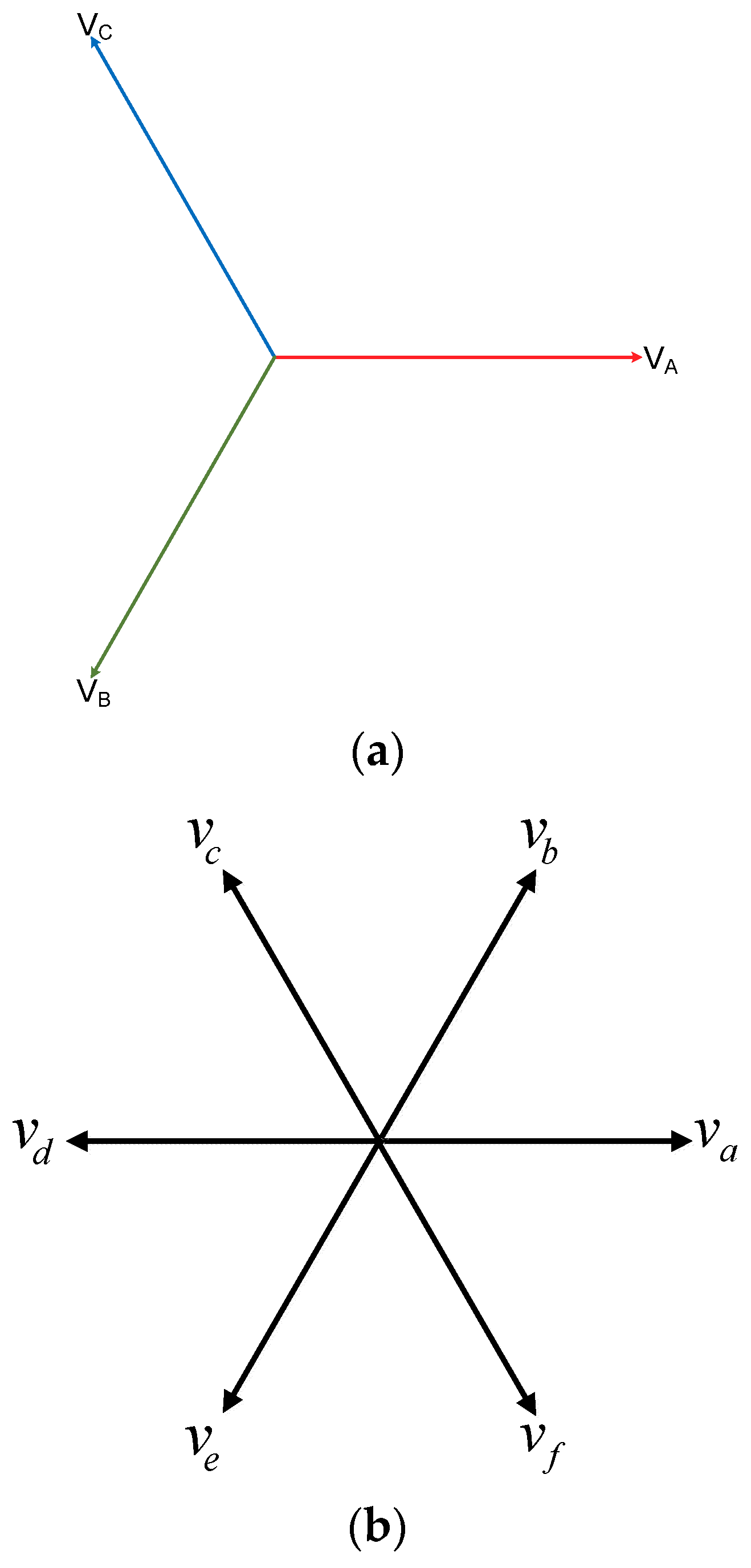
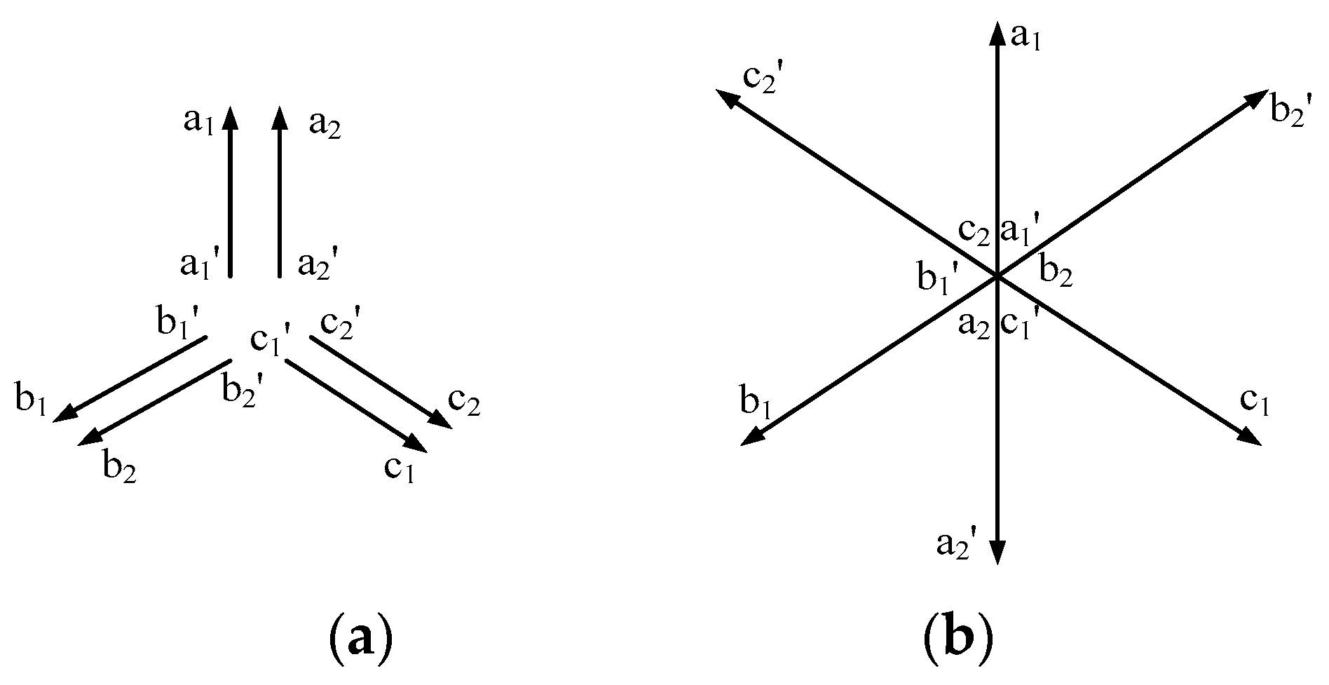
Three-phase input phasors are shown in Figure 1a. In symmetrical six-phase system, each phase is shifted by 60 degrees as shown in Figure 1b. For balanced six-phase system the magnitude of each phase is the same and the phase shift is 60 degree. Asymmetrical six-phase, also called quasi six-phase system, can be considered as set of two three-phase systems with 30 degree phase displacement as shown in Figure 1c. Mathematically, the symmetrical six-phase system is represented as:
The input phases are given as:
The transformation between three-phase input to six-phase output is obtained by using the phase transformation relations given in Equation (1j) considering unity turn ratio.
The two three-phase system can have two separate neutral points or a single neutral point. Mathematically, the quasi six-phase is represented as:
The transformation from three-phase supply to quasi six-phase output is obtained using the relationship given in Equation (2g) considering unity turn ratio.
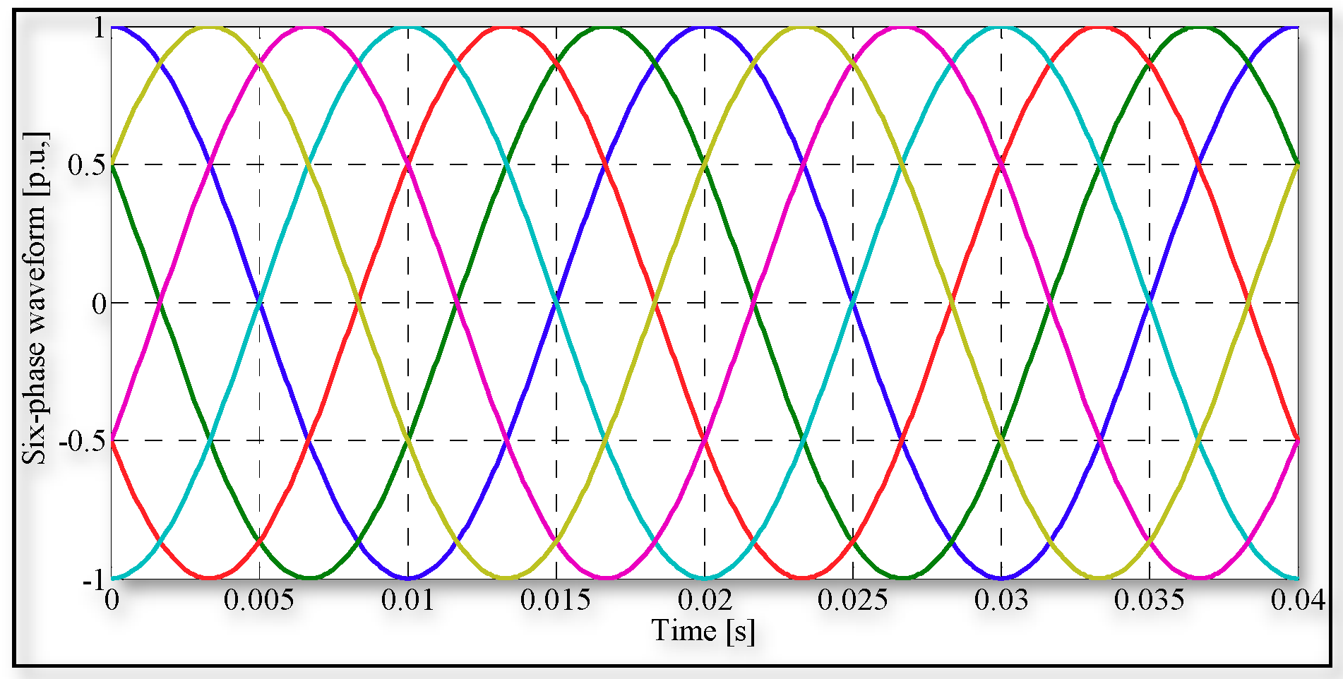
The waveform for a symmetrical six-phase for 50 Hz operation is presented in Figure 2 that shows six-phases with 60 degree phase displacement.
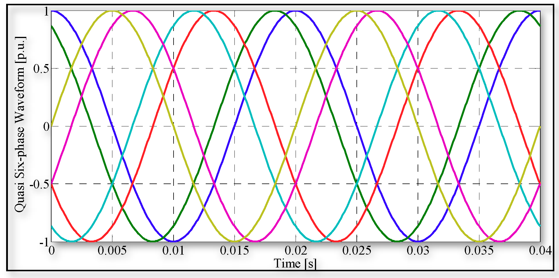
The waveform for quasi six-phase with 50 Hz is presented in Figure 3. Two sets of three-phase output are observed.
3. Space Vector Transformation Six-Phase to Three-Phase System
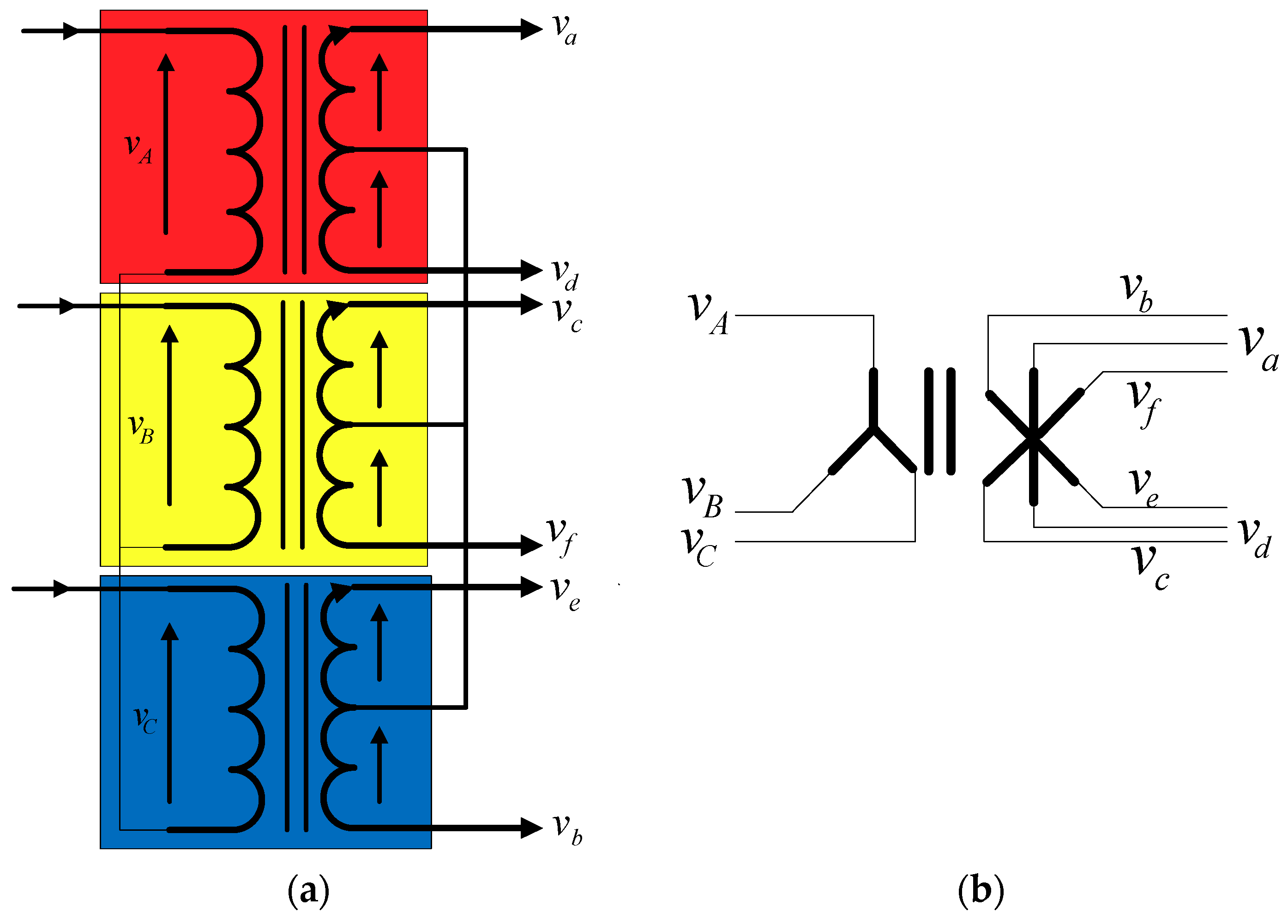
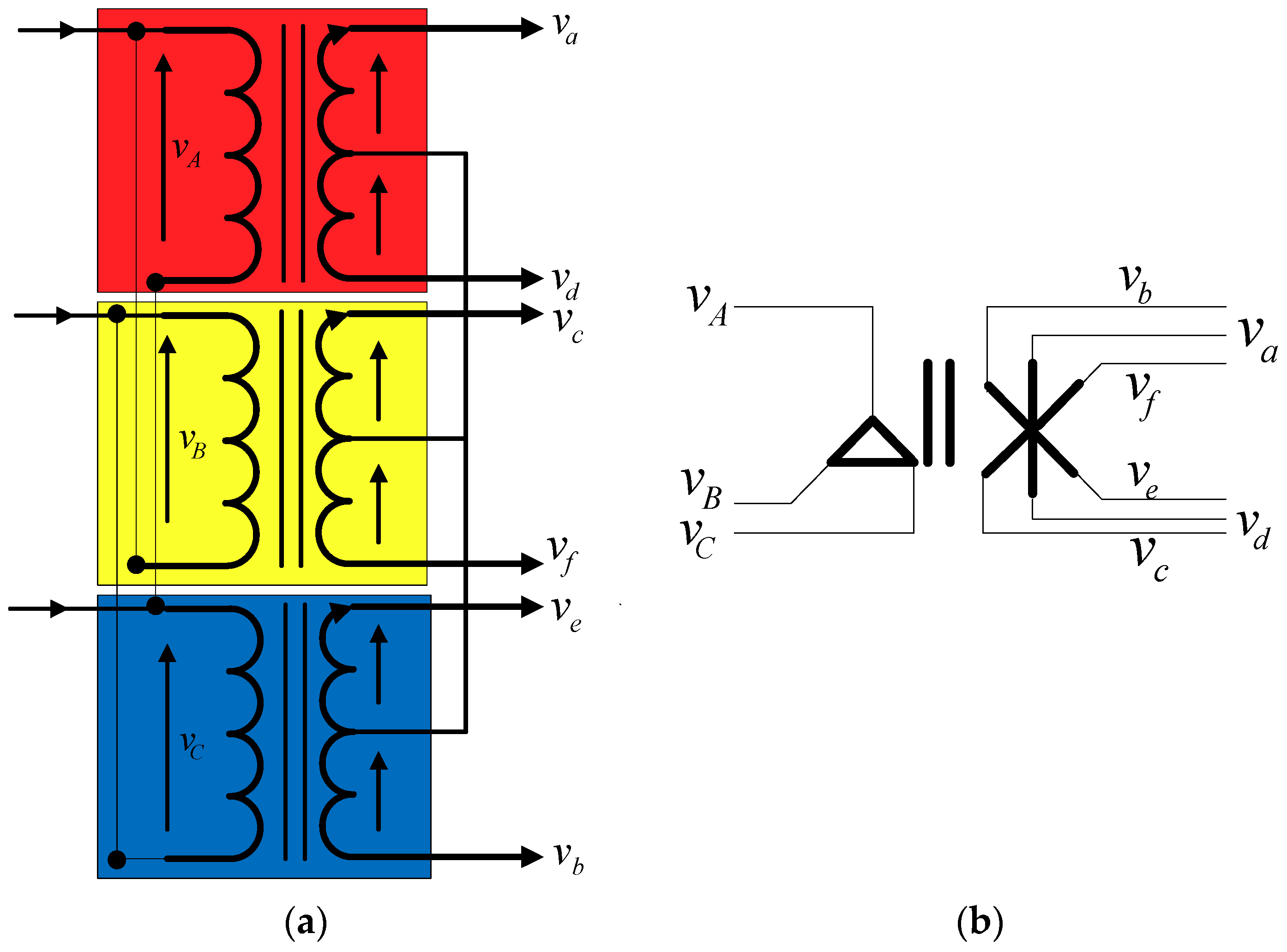
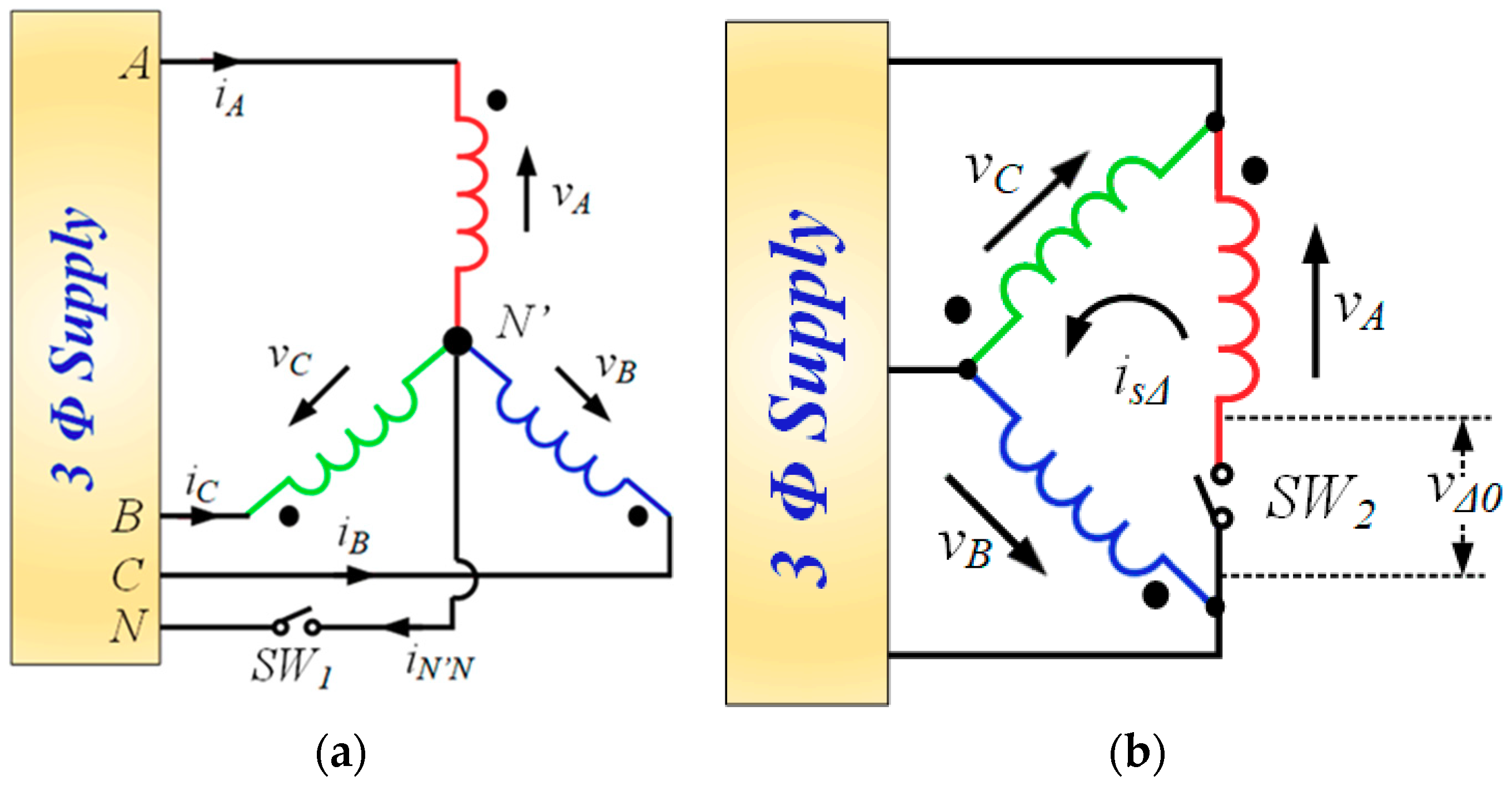
To obtain six-phase supply from three-phase supply, three identical single-phase transformers are needed with a center tap at the secondary. Hence, there are three windings in a single-phase transformer, one primary and two secondary. The primary windings of three single-phase transformers can be connected either in star or in delta. Each half of the secondary winding is considered as a separate phase. The connection diagram for input star and six-phase symmetrical output (60-degree phase displacement) is presented in Figure 4a.
The symbolic representation of this connection scheme is illustrated in Figure 4b. The star point at the input is formed by connecting one terminal of each transformer. The star point at the secondary is formed by connecting the mid-point of the secondary windings. Each half winding of the secondary produces 180 degree displaced voltages. Hence phase ‘a’ and ‘d’ is obtained from first transformer (two opposing output phases). Similarly, output phase ‘c’ and ‘f’ is obtained from second transformer and output phase ‘e’ and ‘b’ is formed from third transformer (refer to Figure 4a). The magnitude of the output voltage is decided by the turn ratio of the transformer. This is further understood from the phasor diagram given in Figure 5. The connection at the primary can also be delta as shown in Figure 5. The connection of primary windings is shown in Figure 5a and the symbolic representation is given Figure 5b. The output will be 30 degree phase shifted compared to the input side or primary side.
Each winding of the secondary produces output voltages as shown in Figure 6a. The two voltages of each single-phase transformer can be used to form two phases of six-phase output. The connection is made in such a way that one voltage is 180 degree phase shifted as shown in Figure 6b. In this way, six-phase outputs are realized.
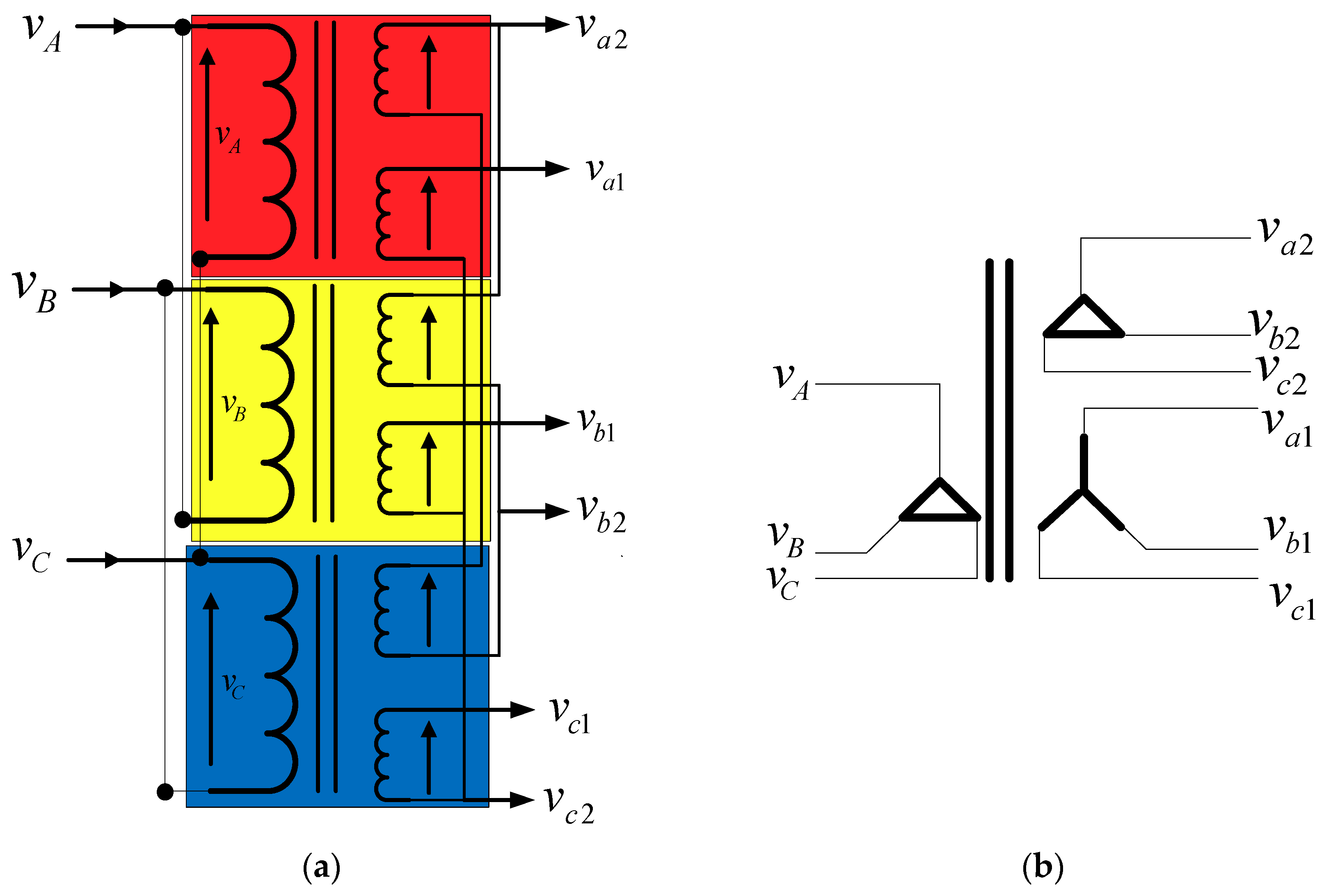
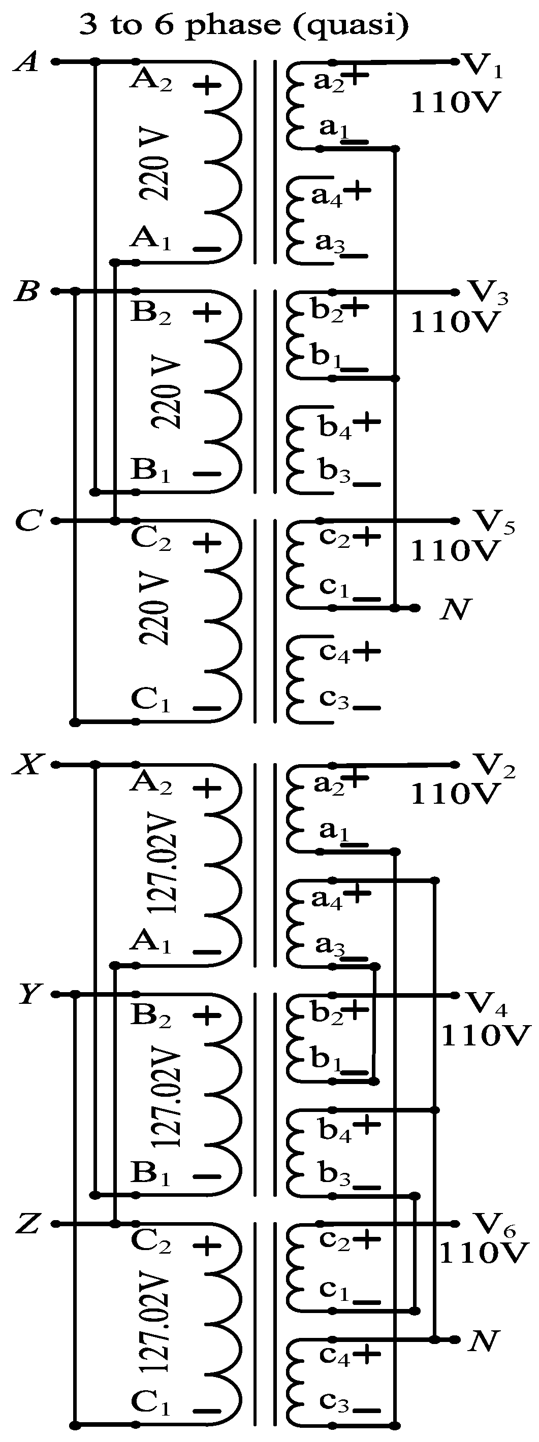
The transformer connection for quasi six-phase output is presented in Figure 7a. The two sets of outputs can be connected in delta and star as shown in Figure 7b. The input is connected in delta and the outputs in star and delta. Due to delta primary, the zero sequence current will not pass on to the secondary. The zero-sequence will be confined to the primary phase windings. Two different types of load can be connected in the secondary. Mix of single and three-phase loads can also be supplied using this connection scheme.
For obtaining quasi six-phase from three single-phase transformer, two set of three-phase are needed to be produced with a phase shift of 30 degrees. This is possible by connecting the primary windings in star and one set of three-phase secondary in star and another set of three-phase secondary windings in delta. In this way, two sets at the output will be obtained. Another possibility is with three-phase input in delta and one set of three-phase secondary in delta and another set of three-phase secondary in star as shown in Figure 7. The output from the delta-connected set is a three-phase system, and the star-connected set (line) is another three-phase output. The phase shift between the primary side delta and secondary side delta will be zero and the secondary voltage magnitude will be half (since the turn ration is 2:1). The phase shift between the primary delta and secondary star (line-to-line) will be 30 degrees. However, the line-to-line voltage magnitude will be √3 * (Primary voltage/2). Although, the two sets of three-phase with 30 degrees phase shift is obtained but the magnitude will not be the same. One set of output coming out from delta connected secondary will be (Primary voltage/2) while the start line-to-line output will be √3 * (Primary voltage/2). Moreover, one set of three-phase will not have a neutral point. In order to get equal magnitude from the two sets, one needs to insert another auto-transformer or normal fixed ratio transformer as shown in Figure 8. Another scheme for getting quasi six-phase output is by using six single-phase transformers as shown in Figure 9. In this scheme the input voltage to the two three-phase input sets should be fed with different magnitude than ones set with ‘Primary voltage’, and another set with ‘Primary voltage/√3’. Hence, quasi six-phase output is obtained in a way that can be used to feed a quasi-six-phase machine.
4. Experimental Parameter Estimation for Single-Phase Transformer Equivalent Circuit
To verify the connection schemes, simulation should be performed. To simulate the used transformer, at first the parameters are obtained experimentally using open circuit test (OCT) and short circuit test (SCT). The used transformer is single-phase with three windings, one on the primary and two on the secondary. The two secondary windings are identical and should have the same parameters. However, the OCT and SCT is conducted for each secondary windings. The experimental data obtained using the OCT and SCT is presented in Table 1.
Shunt branch and series branch parameters can be computed from the readings shown in Table 1.
From OCT:
From SCT for Winding-1:
From SCT for Winding-2
The equivalent circuit is presented in Figure 10.
5. Modeling of a Six-Phase Symmetrical Transformer
The dynamic model of a six-phase transformer is derived and reported in this section. The transformer is a R-L circuit and the generic equation is given as:
where the matrices for primary windings are:
For six-phase secondary windings are:
The resistance matrices are given as:
The flux linkage for the primary and secondary windings are given as:
where are the voltage, current, resistance, self-inductance, and the flux linkage of the three-phase primary windings. The corresponding six-phase secondary windings parameters are .
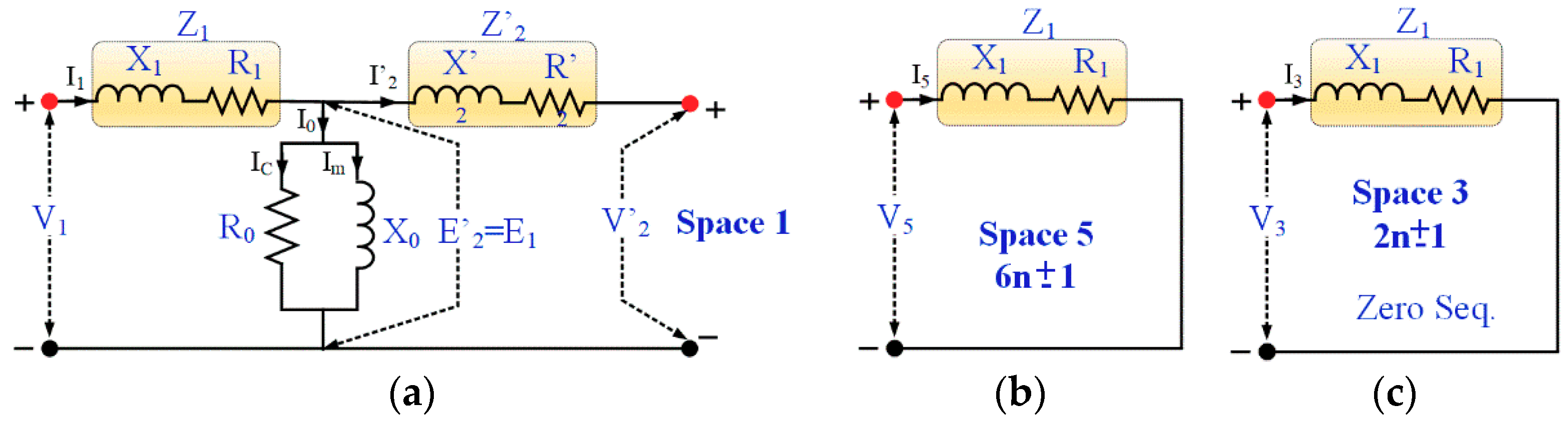
Common Mode Current Flow: If the transformer is supplied using a PWM inverter, the phase variable quantities can be mapped into three orthogonal spaces. First space is actual equivalent circuit of three phase transformer (for fundamental frequency, as shown in Figure 11a). In the second space (space 5, Figure 11b), 5th harmonic, 7th harmonic component etc. are present in the system. However, third space components are homopolar in nature or common mode (Figure 11c). Since the system is balanced, no flow of homopolar component current exists in the system [27].
Zero-sequence (common-mode) voltage and current components for n-phase system is represented as:
To be noted, for a six-phase system only Vo1, Vo2, and Io1, Io2 component will appear in third space vector of the orthogonal space to first- and second-phase. As an obviously under balanced condition on source and load parameters, the third-space vector null and can be neglected from the analysis Equation (11).
6. Numerical Simulation Modeling and Test Results
Performance of three–six phase conversion system is analyzed for sinusoidal input voltage as well as PWM inverter output voltage applied at the primary side of the transformer. These two different configurations of conversion system are tested for six-phase RL and motor loads. For purpose of comparison, conversion system output voltage must be same. For clear explanation, simulation results are classified into two subsections.
6.1. Performance Comparison of Three–Six Phase Conversion System (Symmetrical Six-Phase) with RL Load
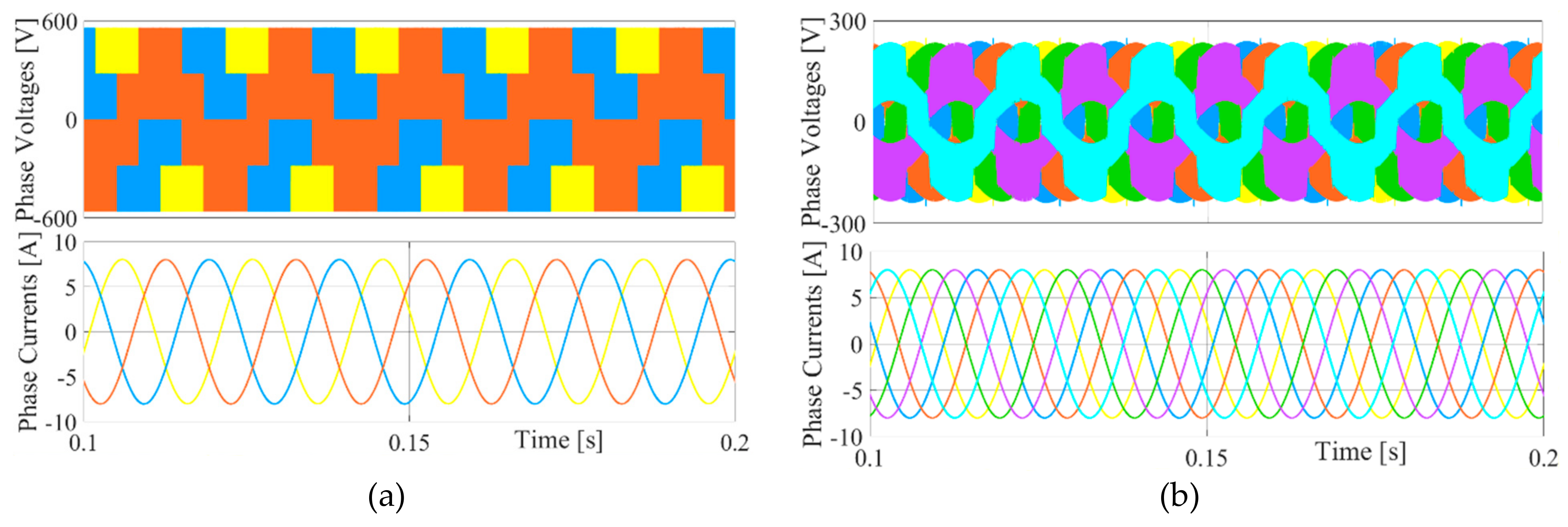
Three–phase PWM inverter is supplied with dc voltage source (650 V) and operated at switching frequency of 10 kHz to give an ac output phase voltage of 220 V rms at the output of the three–six phase conversion system as shown in Figure 12a. Output voltage of PWM inverter is applied as input to the three to six–phase conversion system. For a balanced RL load (20 Ω, 10 mH), six–phase output voltages are obtained. RL load phase voltage and phase current is shown in Figure 12b. RMS voltage of 110 V is obtained at the phase voltage of RL load. Following principle of constant power in the converter system, peak value of input and output currents remains same. From Figure 12a,b, it can be concluded that balanced input and output current are obtained at the three to six–phase conversion system for balanced RL load. For purpose of comparison, three to six–phase conversion system is excited with sinusoidal ac voltage source. Input and output phase voltage and phase current are shown in Figure 12c,d, respectively.
6.2. Performance Comparison of Three–Six Phase Conversion System (Symmetrical Six-Phase) with Six-Phase Motor Load
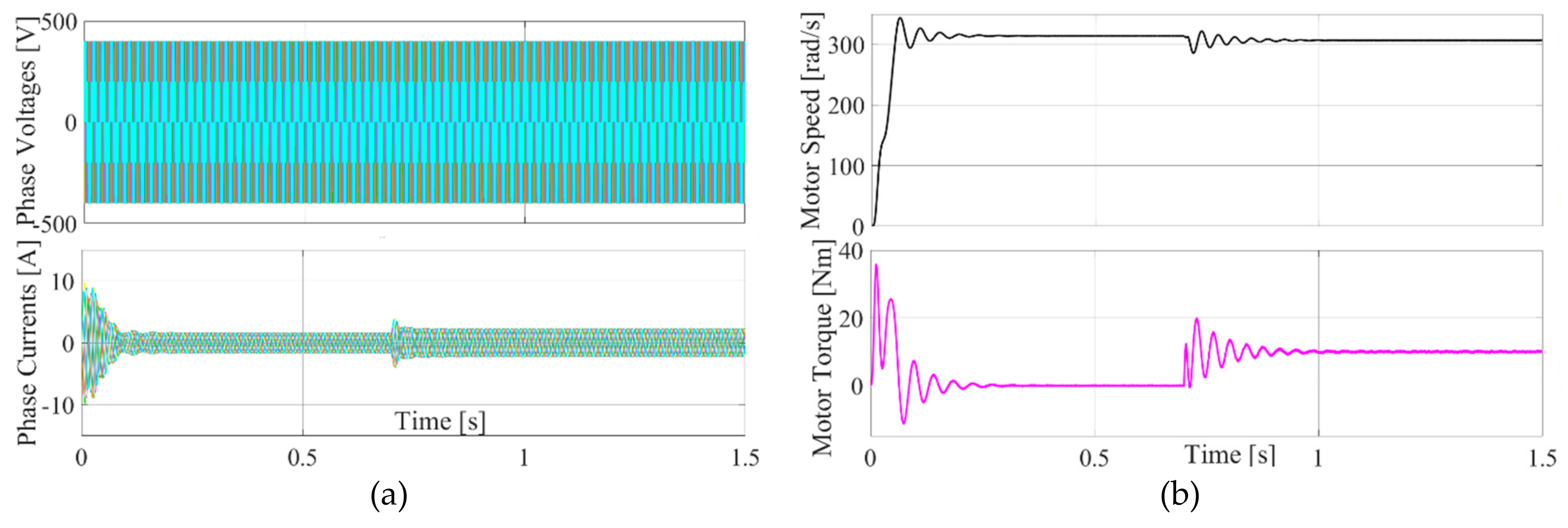
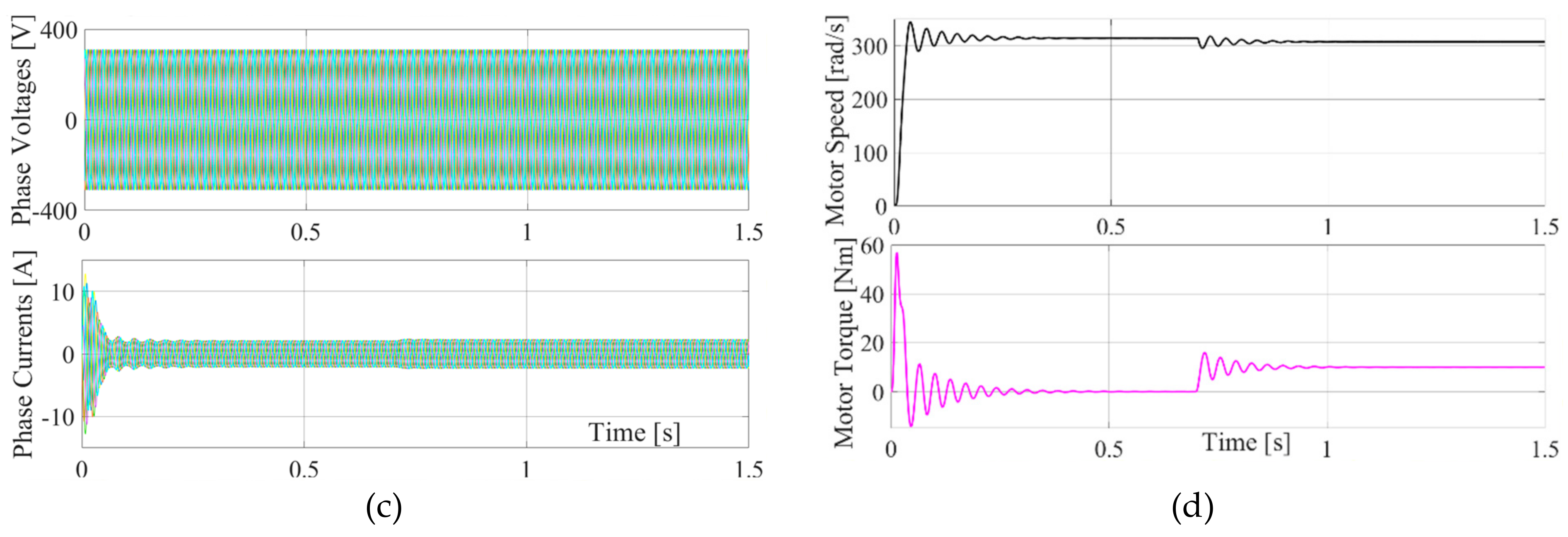
Three–phase PWM is excited with dc bus voltage of 1200 V and operated at 10 kHz switching frequency. This controlled inverter is connected at the input of the three–six phase conversion system. Six–phase motor load is connected at the output of the three–six phase conversion system. Mathematical model of the six-phase induction motor is developed by referring to existing literature [28,29]. Rated input voltage of the motor is 220 V rms. For generation of rotating magnetic field in the six–phase motor, balanced voltage magnitude with proper phase displacement must be generated at the output of the conversion system. Balanced phase voltage applied and stator current obtained are shown in Figure 13a. Motor is started at no load as shown in Figure 13b. At t = 0.7 s, electromagnetic torque of 10 Nm is applied to the motor. This results in increased stator current and speed transients as observed in Figure 13b. For purpose of comparison, six–phase motor is excited with sine supply by means of conversion system. Phase voltage and stator current are shown in Figure 13c. Here also, motor is started at no load and load torque of 10 Nm is applied to the motor at 7 s as shown in Figure 13d. When compared to performance with PWM inverter, ripple in torque is higher due to PWM inverter operation. This is due to higher frequency harmonic components present in applied voltage.
7. Hardware Implementation and Experimental Test Results
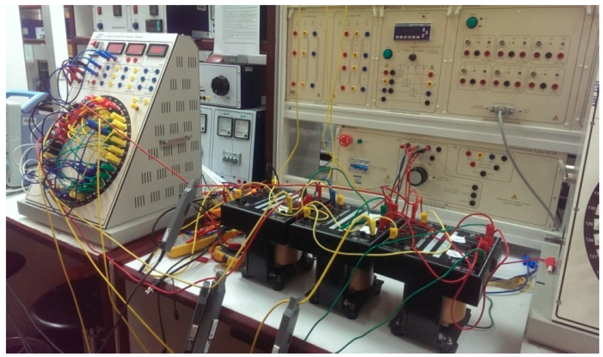
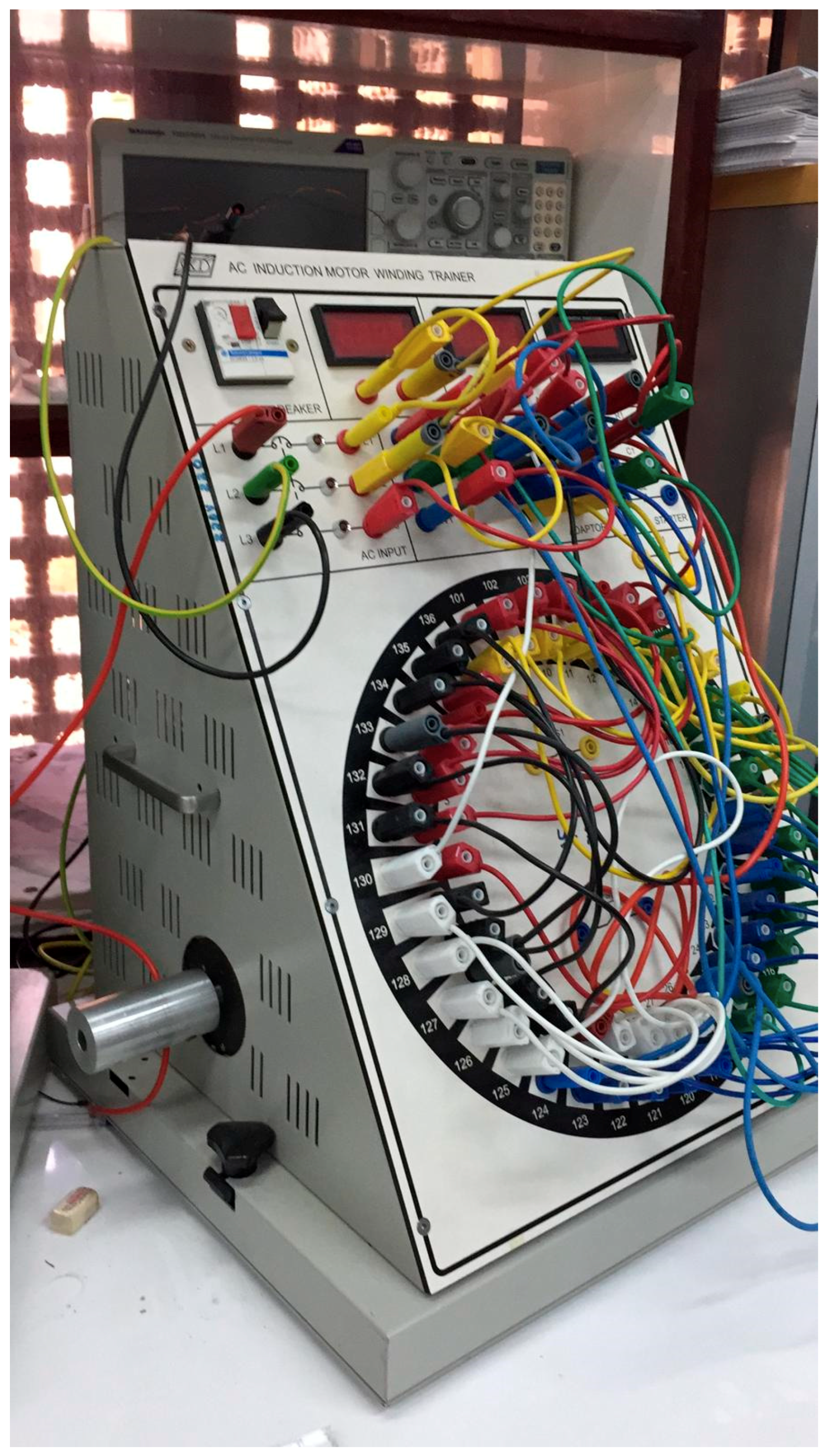
Experimental implementation is done using three single-phase transformers with three windings in each; one primary and two secondary’s. Two connections schemes are implemented; symmetrical six-phase and quasi six-phase. The six-phase output obtained is fed to a six-phase induction motor, which has a 220 V, 1 kW rating. A DC generator is coupled to the shaft of the motor. Resistive load is connected to the terminals of the dc generator to vary the load. The test bench is presented in Figure 14. Three single-phase transformers, one six-phase induction motor (obtained using an induction motor trainer that can is configured as a six-phase machine). Clamp type current sensors can be seen in the set-up as well.
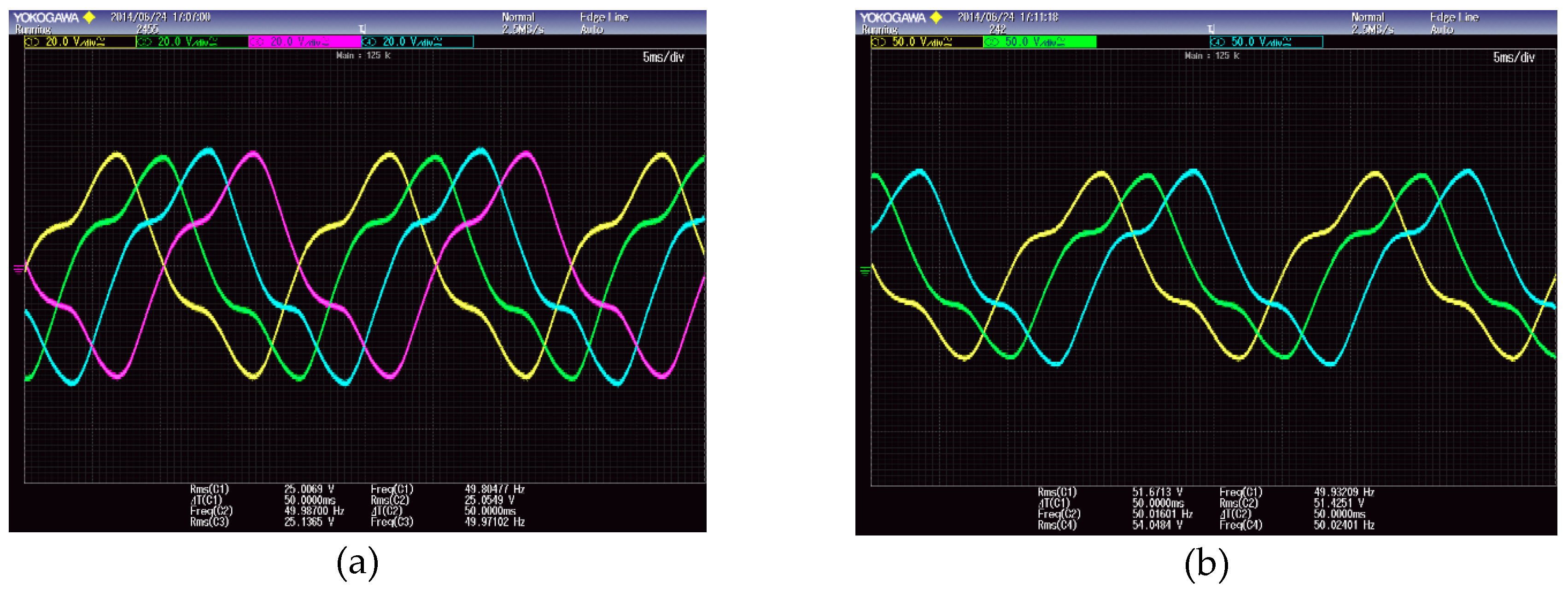
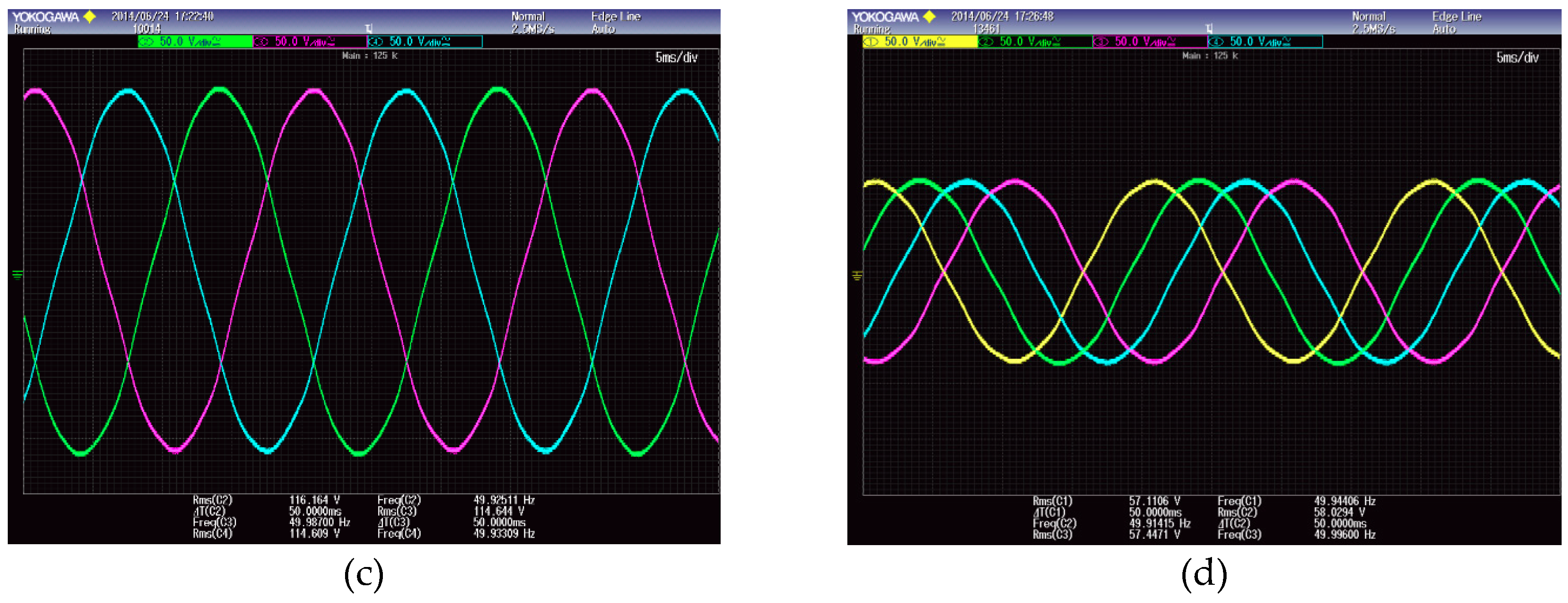
The experimental results are presented in Figure 15a,b for the proposed three to six-phase transformation system. The Figure 15a,b shows the voltage waveforms. The secondary voltages are shown in Figure 15a for the star-connected primary windings and symmetrical six-phase output while the output for the quasi six-phase is presented in Figure 15b. In star-connected primary, the voltage is distorted because grounds are isolated and hence zero sequence current is flowing freely in the secondary sides.
The exciting current is non-sinusoidal and contains harmonics because of non-linear B-H curve. Third harmonic is predominant in the current waveform. At rated voltage, 3rd harmonic component in the exciting current is about 5% to 10% of fundamental [30]. Consider the three-phase supply side with star-connected primary windings and neutral is isolated (not grounded). In this situation, the current flowing through the primary winding contains fundamental components and strong thirds harmonics as given in Equation (12).
where Im1 and Im2 are peak current of fundamental frequency and third harmonic component.
The neutral current is given as:
Due to isolated neutral connection (SW1 open), the third harmonic current is present in the three-phase primary side. This harmonic component causes distortion of the overall current. The presence of 3rd harmonic current in the star-connected primary winding is shown in Figure 15a. On the other hand, the 3rd harmonic current in a delta-connected primary winding circulate in the closed-loop of the three-phase winding as shown in Figure 15b. Since the 3rd harmonic current confines to the phase windings, they are not reflected in the line side. The outputs from both symmetrical and quasi six-phase are distorted since the primary winding is the same. The results with delta-connected primary and symmetrical six-phase output and quasi six-phase output are shown in Figure 16c,d, respectively. The outputs are sinusoidal in both the cases. In delta-connected primary, the voltage is sinusoidal because the zero-sequence current does not flow in the line and they are restricted to the phase only.
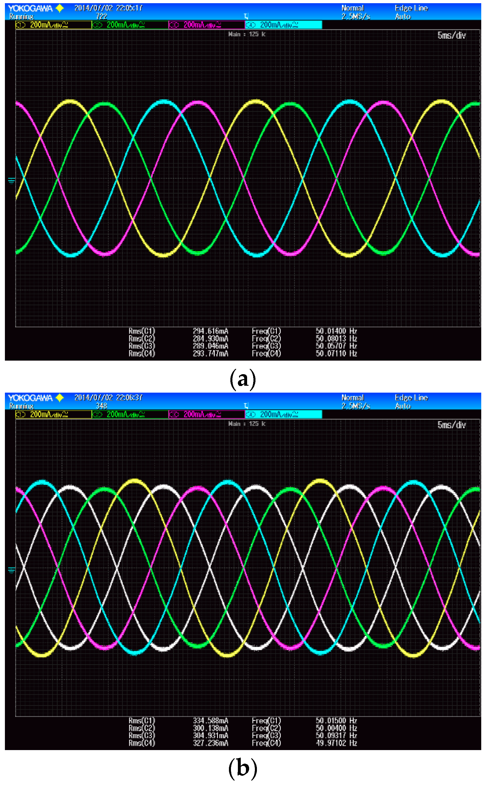
The six-phase symmetrical motor is obtained by connecting the modular stator windings in such as a way that 4-pole six-phase windings with 60° phase shift is achieved. There are 36 slots with double layer winding. The winding disposition can be seen from Figure 17. The rotor is squirrel cage type. The symmetrical six-phase motor is supplied by the proposed six-phase transformer. The stator winding currents are presented in Figure 18a,b. Two conditions are presented; no-load and full-load. There is a slight unbalance in the windings, which becomes prominent for full-load condition. The unbalancing is due to practical asymmetry in the stator winding of the motor.
8. Conclusions
Multiphase system is increasingly employed in generation, transmission and utilization of electrical energy. Multiphase system may be incorporated in the course of electrical machines at undergraduate level of education. This paper presented the basic concept of phase conversion from three-phase to six-phase using transformer connection. The theoretical description is supported by simulation results and experimental verification. Such experiments could be conducted in the courses providing the students with hands-on experience with a concept that has a promising future. This paper has provided how such a concept could be made to be understood with doable experiments, which was missing in many literature reviews. The presented system will enhance the learning of the advanced concept, which seems a promising technology in near future.
Author Contributions
Experiments were designed by R.A.-A., A.I., S.P.; Experiments were performed by A.I., A.K., S.R.; Results were analyzed by all authors. All authors were involved in interpretation of data and paper writing.
Funding
This research received no external funding.
Acknowledgments
The publication of this article was funded by the Qatar National Library, Doha, Qatar.
Conflicts of Interest
The authors certify that they have no affiliations with or involvement in any organization or entity with any financial interest or non-financial interest in the subject matter or materials discussed in this manuscript.
References
- Rodriguez-Ponce, R.; Gomez-Loenzo, R.A.; Rodriguez-Resendiz, J. A project-oriented approach for power electronics and motor drive courses. Int. J. Electr. Eng. Educ. 2015, 52, 219–236. [Google Scholar] [CrossRef]
- Ekinci, S.; Zeynelgil, H.L.; Demiroren, A. A didactic procedure for transient stability simulation of a multi-machine power system utilizing SIMULINK. Int. J. Electr. Eng. Educ. 2016, 53, 54–71. [Google Scholar] [CrossRef]
- Garcia, I.; Guzmán-Ramírez, E.; Guerrero, E.; Pacheco, C. An educational tool for designing DC motor control systems through FPGA-based experimentation. Int. J. Electr. Eng. Educ. 2015, 52, 22–38. [Google Scholar]
- Riba, J.-R.; Garcia, A.; Romeral, L. A computer experiment to simulate the dynamic behaviour of electric vehicles driven by switched reluctance motors. Int. J. Electr. Eng. Educ. 2014, 51, 368–382. [Google Scholar] [CrossRef]
- Toukhtarian, R.; Sanjab, A.; Saab, S. On the model order reduction of a direct current motor. Int. J. Electr. Eng. Educ. 2015, 52, 52–70. [Google Scholar] [CrossRef]
- Montes, A.J.S.; Castro, H.A.B.; Riveros, J.A.H. How to motivate students to work in the laboratory: A new approach for an electrical machines laboratory. IEEE Trans. Educ. 2010, 53, 490–496. [Google Scholar] [CrossRef]
- Chin, Y.; Chang, G. An integrated on-line system for experimental data analysis to electric machines laboratory. In Proceedings of the 2007 International Power Engineering Conference (IPEC 2007), Singapore, 3–6 December 2007; pp. 1416–1420. [Google Scholar]
- Gedra, T.W.; An, S.; Arsalan, Q.H.; Ray, S. Unified power engineering laboratory for electromechanical energy conversion, power electronics, and power systems. IEEE Trans. Power Syst. 2004, 19, 112–119. [Google Scholar] [CrossRef]
- Consonni, D.; Seabra, A.C. A modern approach to teaching basic experimental electricity and electronics. IEEE Trans. Educ. 2001, 44, 5–15. [Google Scholar] [CrossRef]
- Li, S.; Challoo, R. Restructuring an electric machinery course with an integrative approach and computer-assisted teaching methodology. IEEE Trans. Educ. 2006, 49, 16–28. [Google Scholar] [CrossRef]
- Savander-Ranne, C.; Lundén, O.-P.; Kolari, S. An alternative teaching method for electrical engineering courses. IEEE Trans. Educ. 2008, 51, 423–431. [Google Scholar] [CrossRef]
- Bentounsi, A.; Djeghloud, H.; Benalla, H.; Birem, T.; Amiar, H. Computer-aided teaching using MATLAB/Simulink for enhancing an IM course with laboratory tests. IEEE Trans. Educ. 2011, 54, 479–491. [Google Scholar] [CrossRef]
- Ayasun, S.; Nwankpa, C.O. Induction motor tests using MATLAB/Simulink and their integration into undergraduate electric machinery courses. IEEE Trans. Educ. 2005, 48, 37–46. [Google Scholar] [CrossRef]
- Nehrir, M.H.; Fatehi, F.; Gerez, V. Computer modeling for enhancing instruction of electric machinery. IEEE Trans. Educ. 1995, 38, 166–170. [Google Scholar] [CrossRef]
- Kothari, D.P.; Nagrath, I. Electric Machines; Tata McGraw-Hill Education: New Delhi, India, 2004. [Google Scholar]
- Iqbal, A.; Moinuddin, S.; Khan, M.R.; Ahmed, S.M.; Abu-Rub, H. A novel three-phase to five-phase transformation using a special transformer connection. IEEE Trans. Power Deliv. 2010, 25, 1637–1644. [Google Scholar] [CrossRef]
- Moinoddin, S.; Iqbal, A.; Abu-Rub, H.; Khan, M.R.; Ahmed, S.M. Three-phase to seven-phase power converting transformer. IEEE Trans. Energy Convers. 2012, 27, 757–766. [Google Scholar] [CrossRef]
- Warathe, S.; Patel, R. Six-phase transmission line over current protection by numerical relay. In Proceedings of the 2015 International Conference on Advanced Computing and Communication Systems, Coimbatore, India, 5–7 January 2015; pp. 1–5. [Google Scholar]
- Koley, E.; Jain, A.; Thoke, A.; Jain, A.; Ghosh, S. Detection and classification of faults on six phase transmission line using ANN. In Proceedings of the 2011 2nd International Conference on Computer and Communication Technology (ICCCT), Allahabad, India, 15–17 September 2011; pp. 100–103. [Google Scholar]
- Yan, X.; Xu, Z.; Wen, A.; Yang, Q. Fault analysis principle for twelve-phase transmission system. In Proceedings of the 2012 IEEE Power and Energy Society General Meeting, San Diego, CA, USA, 22–26 July 2012; pp. 1–6. [Google Scholar]
- Dorazio, T. High phase order transmission. In Proceedings of the 1990 IEEE Southern Tier Technical Conference, Binghamton, NY, USA, 25 April 1990; pp. 31–36. [Google Scholar]
- Xu, P.; Wang, G.; Li, H.; Liang, Y.; Zhang, P. A new method for open conductors fault calculation of four-parallel transmission lines. In Proceedings of the 2010 Asia-Pacific, Power and Energy Engineering Conference (APPEEC), Chengdu, China, 28–31 March 2010; pp. 1–4. [Google Scholar]
- Wen, J.; Qin, H.; Wang, S.; Zhou, B. Basic connections and strategies of isolated phase-shifting transformers for multipulse rectifiers: A review. In Proceedings of the 2012 Asia-Pacific Symposium on, Electromagnetic Compatibility (APEMC), Singapore, 21–24 April 2012; pp. 105–108. [Google Scholar]
- Singh, B.; Gairola, S.; Singh, B.N.; Chandra, A.; Al-Haddad, K. Multipulse AC–DC converters for improving power quality: A review. IEEE Trans. Power Electron. 2008, 23, 260–281. [Google Scholar] [CrossRef]
- Levi, E. Multiphase electric machines for variable-speed applications. IEEE Trans. Ind. Electron. 2008, 55, 1893–1909. [Google Scholar] [CrossRef]
- Singh, G. Multi-phase induction machine drive research—A survey. Electr. Power Syst. Res. 2002, 61, 139–147. [Google Scholar] [CrossRef]
- Sen, P.C. Principles of Electric Machines and Power Electronics; John Wiley & Sons: Chichester, UK, 2007. [Google Scholar]
- Grandi, G.; Tani, A.; Sanjeevikumar, P.; Ostojic, D. Multi-phase multi-level AC motor drive based on four three-phase two-level inverters. In Proceedings of the SPEEDAM 2010, Pisa, Italy, 14–16 June 2010; pp. 1768–1775. [Google Scholar]
- Rinkevičienė, R.; Savickienė, Z.; Uznys, D.; Pitrėnas, A.; Šlepikas, A. Scalar control of six-phase induction motor. In Proceedings of the 2017 Open Conference of Electrical, Electronic and Information Sciences (eStream), Vilnius, Lithuania, 27 April 2017; pp. 1–6. [Google Scholar]
- Abbas, M.A.; Christen, R.; Jahns, T.M. Six-Phase Voltage Source Inverter Driven Induction Motor. IEEE Trans. Ind. Appl. 1984, IA-20, 1251–1259. [Google Scholar] [CrossRef]
Figure 1.
(a) Three-Phase Phasor Diagram; (b) symmetrical Six-phase Phasor Diagram; (c) asymmetrical Six-phase Phasor Diagram.
Figure 1.
(a) Three-Phase Phasor Diagram; (b) symmetrical Six-phase Phasor Diagram; (c) asymmetrical Six-phase Phasor Diagram.


Figure 2.
Symmetrical six-phase output.

Figure 3.
Asymmetrical or quasi six-phase output.

Figure 4.
Symmetrical six-phase output with primary star; (a) connection diagram; (b) symbolic representation.
Figure 4.
Symmetrical six-phase output with primary star; (a) connection diagram; (b) symbolic representation.

Figure 5.
Six-phase output with primary delta; (a) connection diagram; (b) symbolic representation.

Figure 6.
Output voltage phasors (a) Representation 1 (b) Representation 2.

Figure 7.
Quasi six-phase output with primary delta; (a) connection diagram; (b) symbolic representation.
Figure 7.
Quasi six-phase output with primary delta; (a) connection diagram; (b) symbolic representation.

Figure 8.
Obtaining equal magnitudes two sets of three-phase outputs with 30° phase shifts.

Figure 9.
Obtaining equal magnitudes two sets of three-phase outputs with 30° phase shifts.

Figure 10.
Equivalent circuit of single-phase transformer for fundamental frequency.

Figure 11.
Equivalent circuit of single-phase transformer.

Figure 12.
(a) Phase voltage [V] and phase current [A] at the primary side (with PWM inverter); (b) phase Voltage [V] and Phase current [A] at the secondary side (with PWM inverter); (c) phase voltage and phase current at the primary side (with sine ac voltage source); and (d) phase Voltage and Phase current at the secondary side (with sine ac voltage source).


Figure 13.
(a) Six–phase balanced phase voltage [V] and phase current [A] at the primary side (with PWM inverter); (b) mechanical speed [rad/sec] and electromagnetic torque [N-m] of the six–phase motor (with PWM inverter); (c) six–phase balanced phase voltage [V] and phase current [A] at the secondary side (with sine ac voltage source); and (d) mechanical speed [rad/sec] and electromagnetic torque [N-m] of the six – phase motor (with sine ac voltage source).


Figure 14.
Experimental set-up.

Figure 15.
Presence of 3rd harmonic current in the (a) star-connected primary windings and (b) delta-connected primary windings.
Figure 15.
Presence of 3rd harmonic current in the (a) star-connected primary windings and (b) delta-connected primary windings.

Figure 16.
(a) Symmetrical six-phase output with star-connected primary; (b) quasi six-phase output with primary in star; (c) symmetrical six-phase output with Delta-connected primary; (d) quasi six-phase output with delta-connected primary.
Figure 16.
(a) Symmetrical six-phase output with star-connected primary; (b) quasi six-phase output with primary in star; (c) symmetrical six-phase output with Delta-connected primary; (d) quasi six-phase output with delta-connected primary.


Figure 17.
Six-phase motor.

Figure 18.
(a) Symmetrical Six-phase motor under no-load condition; (b) symmetrical motor under full-load condition.
Figure 18.
(a) Symmetrical Six-phase motor under no-load condition; (b) symmetrical motor under full-load condition.


Table 1.
Readings from open-circuit and short-circuit test.
| Primary Side | Secondary Side-1 | Secondary Side-2 |
|---|---|---|
| Vo = 220 Volts | Vsc = 15.1 V | Vsc = 14.2 V |
| Ioc = 0.34 A | Isc = 4.55 A | Isc = 4.56 A |
| Poc = 24.5 W | Psc = 66 W | Psc = 63 W |
© 2019 by the authors. Licensee MDPI, Basel, Switzerland. This article is an open access article distributed under the terms and conditions of the Creative Commons Attribution (CC BY) license (http://creativecommons.org/licenses/by/4.0/).
Share and Cite
MDPI and ACS Style
Al-Ammari, R.; Iqbal, A.; Khandakar, A.; Rahman, S.; Padmanaban, S. Systematic Implementation of Multi-Phase Power Supply (Three to Six) Conversion System. Electronics 2019, 8, 109. https://doi.org/10.3390/electronics8010109
AMA Style
Al-Ammari R, Iqbal A, Khandakar A, Rahman S, Padmanaban S. Systematic Implementation of Multi-Phase Power Supply (Three to Six) Conversion System. Electronics. 2019; 8(1):109. https://doi.org/10.3390/electronics8010109
Chicago/Turabian StyleAl-Ammari, Rashid, Atif Iqbal, Amith Khandakar, Syed Rahman, and Sanjeevikumar Padmanaban. 2019. "Systematic Implementation of Multi-Phase Power Supply (Three to Six) Conversion System" Electronics 8, no. 1: 109. https://doi.org/10.3390/electronics8010109
Note that from the first issue of 2016, this journal uses article numbers instead of page numbers. See further details here.