


Numerical Modelling of Double-Twisted Wire Mesh for Low-Energy Rockfall Catch Fences

1
QTS Group Ltd., Glasgow ML10 6QJ, UK
2
James Watt School of Engineering, University of Glasgow, Glasgow G12 8QQ, UK
*
Author to whom correspondence should be addressed.
Geosciences 2023, 13(6), 180; https://doi.org/10.3390/geosciences13060180
Submission received: 16 February 2023
/
Revised: 5 May 2023
/
Accepted: 31 May 2023
/
Published: 15 June 2023
(This article belongs to the Special Issue Rockfall Protection and Mitigation)
Abstract
:Low-energy rockfall catch fences are designed to protect infrastructure such as railways and roads wherein the kinetic energy of falling rocks is less than 100 kJ. The typical design consists of a double-twisted steel wire mesh supported by ground posts and strengthened by anchoring wire ropes. The fence stops falling rocks by dissipating the impact energy mainly through elastoplastic stretching of steel wires in the mesh. In this study, a three-dimensional finite element model for double-twisted wire mesh was developed in Abaqus/Explicit. The model has been verified using both quasi-static loading and impact tests. It was found that proper geometrical representation is essential for accurate simulation of wire deformation modes and the interaction between double-twisted wires. The model also enables the application of the real stress–strain relationship of a single steel wire in constitutive models.
1. Introduction
The records of the national landslide database provided by the British Geological Survey (BGS) for Great Britain [1] show that there has been a significant rise in the number of rockfall incidents in the UK in recent years (Figure 1). In many locations along UK railways, there is a significant risk of falling rocks reaching the infrastructure, causing the derailment of trains, and damage to tracks and signalling systems [2].
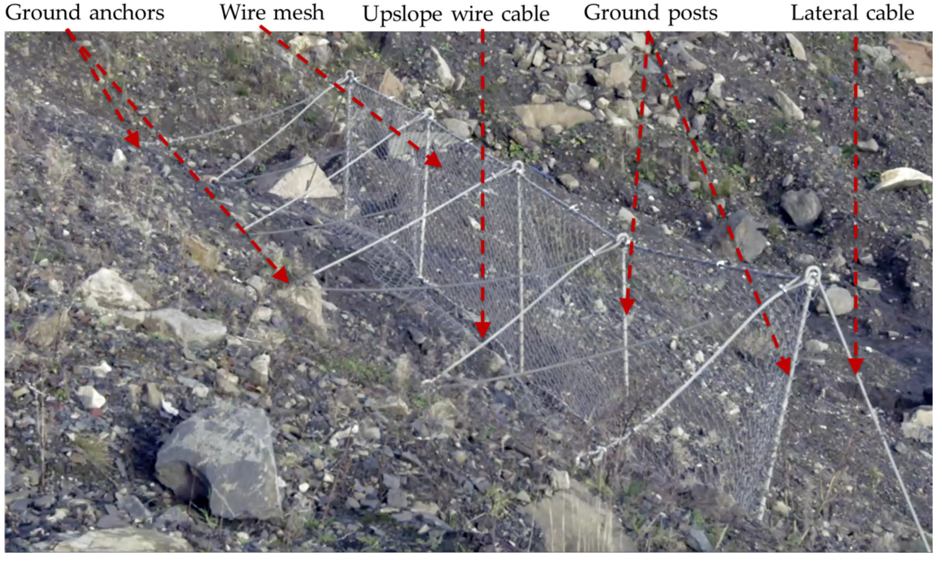
Rockfall hazards can be mitigated by various means, including catch fences, which consist of steel wire meshes, cables, and ground supporting posts, etc. (see Figure 2). Compared to other rockfall mitigation methods, catch fences offer many advantages, including a shorter construction time, reduced visual impact, and lower maintenance costs. Catch fences can be classified as high (or low)-energy dissipation systems based on their capacity to dissipate the energy of rockfalls above (or below) an impact energy threshold of 100 kJ. In general, high-energy catch fences are semi-rigid, permanent structures, and are designed according to established guidelines [3,4]. These high-cost systems are not normally required in the UK, where most rockfall incidents may be classified as low-energy. Under these conditions, a non-permanent catch fence system, as shown in Figure 2, can offer adequate protection at a lower cost. This lightweight system can be installed manually, without recourse to mechanised plants. It dissipates the impact energy of falling objects through plastic deformation of the flexible wire mesh and the posts, which must then be replaced.
The design of low-energy catch fences, which have received far less attention [5,6,7] than high-energy systems, is based primarily on field tests and engineering judgements. Numerical models for high-energy catch fences have perforce paid particular attention to material failure mechanisms [8,9,10] and energy dissipation capacities [11,12,13,14]. Although similar numerical modelling approaches have been used to simulate low-energy systems [15,16], several issues require further investigation.
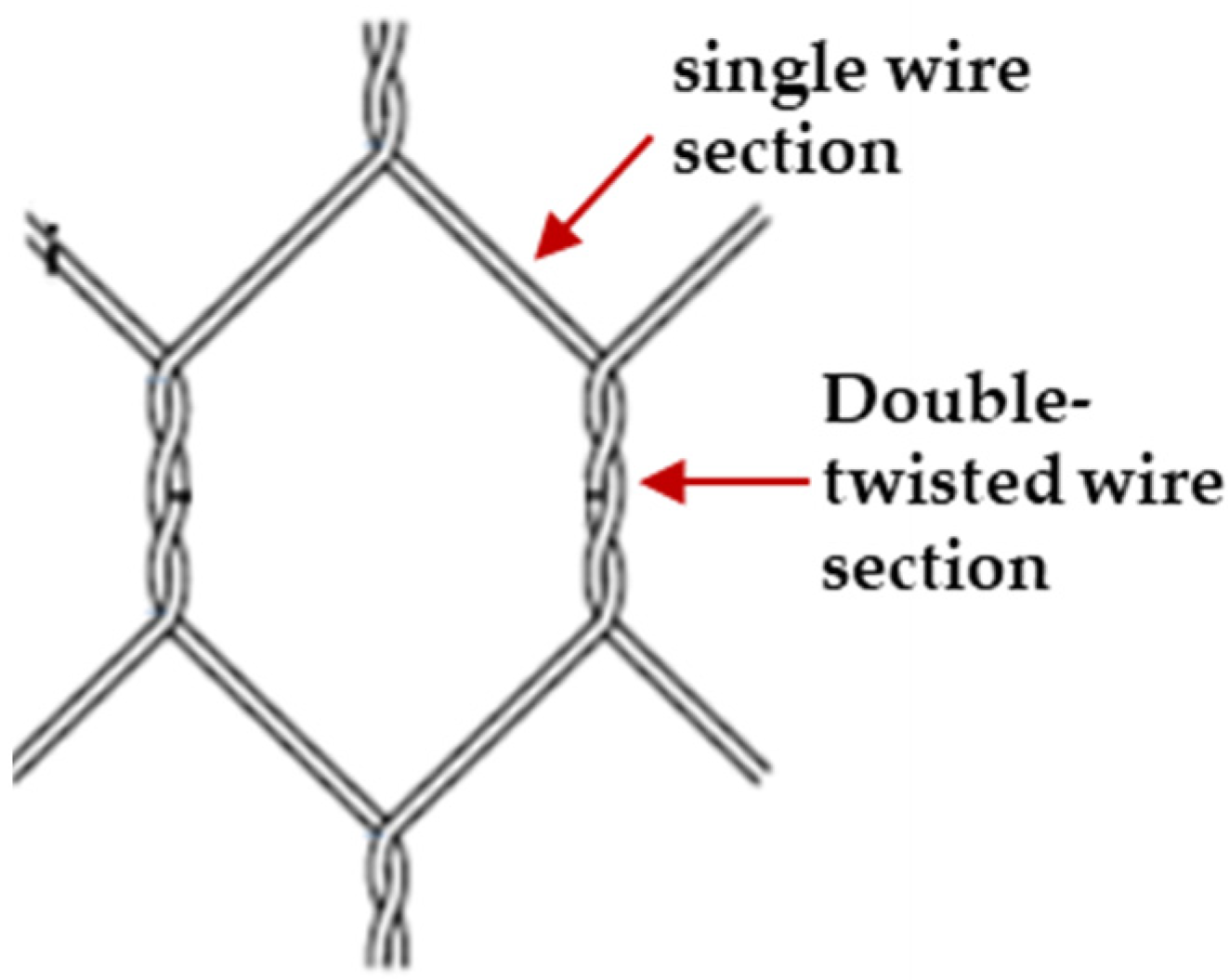
First, in the studies cited above, the modelling of double-twisted wire mesh has been simplified to reduce the difficulties and computing time of geometrical modelling. Double-twisted wire mesh consists of symmetrically woven hexagonal cells, wherein each cell has four sections (sides) of single wires and two sections of twisted wires, as shown in Figure 3. The structure of the cells affects the macroscopic strength and flexibility of the whole mesh. When a wire mesh is subjected to an impact, the wires in the double-twisted sections stretch and twist simultaneously. The impact energy is dissipated through friction between the double-twisted wires and through elastoplastic stretching of individual wires. If the impact load exceeds the material strength, single-wire sections become damaged, which causes the unravelling of the adjacent wires, which itself degrades the response of nearby cells. This zone of degradation increases with increasing impact load. These interactions cannot be simulated accurately if the finite element (FE) model of the double-twisted section is represented using a single-beam element [8,15]. A similar issue occurs when representing the terminal ends of the twisted sections with discontinuous nodes, when employing the discrete element approach [9,10,13,14,16].
A second issue relates to the material modelling of the steel wires. Simplified models that define a failure criterion in terms of global measures, such as the maximum deformation of the mesh [3,4], risk failing to capture the important elements of system response, particularly in cases wherein the impact scenario differs from the tests used for parameter calibration purposes [15]. A proper constitutive model for describing the mechanical response of a single wire is needed.
In this paper, a detailed analysis of a double-twisted hexagonal wire mesh is presented. A direct modelling approach in the three-dimensional space is used to create the wire mesh model, which is then analysed using Abaqus/Explicit [17]. The material constitutive model is based on experimental tests on single wires cut out from the wire meshes. In adopting this rigorous approach, we aim to better understand the response of low-energy catch fences to impact, and thereby to contribute to improving design methods.
2. Numerical Modelling of the Double-Twisted Wire Mesh
A three-dimensional model of a double-twisted hexagonal wire mesh has been analysed using Abaqus/Explicit [17]. Full advantage was taken of its capability to handle highly non-linear geometric and material responses under dynamic loading conditions.
2.1. Geometrical Representation
An explicit model of Maccaferri [18] double-twisted hexagonal 2.7 mm diameter wire mesh was created, with cell dimensions of 80 mm × 100 mm, referred to as P8/2.7. SolidWorks CAD software [19] was used to create the geometry of each twisted wire separately, which was then exported into Abaqus.
As each wire consists of straight and twisted sections, its geometry can be created from connected straight and twisted segments to form a 3D sketch path. This simplified approach creates a discrete geometrical representation of the wires, as shown in Figure 4a. This leads to convergence difficulties and inaccuracies in the calculation of the directional components when the finite element model is created. This is because the normal sections and cross-sections of neighbouring wire elements are not collinear at the connection points. Consequently, wires are created as a single continuous geometry with no interconnection points, which represents the wire mesh length, as shown in Figure 4b.
In practice, wires are coated with a PVC layer to enhance their weather resistance; this layer is not modelled geometrically, but its effect on frictional resistance can be considered.
When a double-twisted mesh panel is subjected to impact, its wires, particularly those in the double-twisted sections, stretch, twist and bend. To reproduce these deformations in the numerical model, the Timoshenko beam element was used. This element can simulate three modes of deformation: axial stretching, bending (change in curvature), and twisting in three-dimensional space. This element has an advantage over the other elements, having simpler geometry and better computational efficiency.
In addition, Abaqus has a powerful and robust beam-to-beam contact algorithm which simulates the contact between the surfaces of beams rather than their centrelines. This is achieved by specifying the radius of the beam (wire). The algorithm uses penalty-based contact constraints to enforce the contact behaviour between the surfaces. The penalty-based contact algorithm works by applying a penalty force to the nodes of the beam element that are in contact with the surface with which the beam is in contact. However, a modelling difficulty is that Abaqus assumes that these beam elements are initially straight, which complicates the representation of the double-twisted sections. To resolve this difficulty, a curvature control feature in Abaqus, which increases the number of elements wherein the curvature is high, is used. It calculates the seed distribution based on the curvature of the edge along with the target element size. With this tool, users can specify the deviation factor, which is a measure of how much the element edges deviate from the original geometry. As the deviation factor reduces, the number of elements that Abaqus/CAE create around the curve will increase. A convergence study was conducted to identify the optimum deviation factor for the double-twisted wire mesh and the optimum (straight) element size.
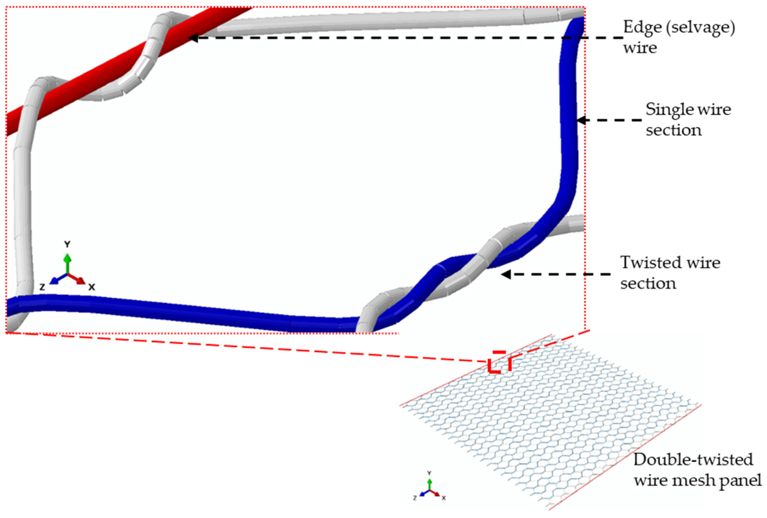
A typical model of a hexagonal double-twisted wire mesh panel with an optimal element size and element distribution is shown in Figure 5. The edge wire (selvedge wire) is also presented, and has a larger diameter than the mesh itself.
2.2. Constitutive Model for Single Steel Wires
An elastoplastic constitutive model is considered in Abaqus/Explicit to describe the material behaviour of the double-twisted wire mesh. The model also accounts for material failure, wherein damage initiation and damage evaluation criteria were implemented.
To determine the necessary parameters for the elastoplastic constitutive and material failure model, a series of uniaxial tensile tests were carried out on single wires using a uniaxial testing machine (Instron 3369) and a video-extensometer (LIMESS RTSS) for optical strain measurements. The preparation of the test specimens and the test setup are shown in Figure 6. The effective length of the specimens was similar to the single wire sections in the mesh cells. The test specimens were taken from a mesh panel and straightened carefully, in order to avoid twisting the 60 mm test section (highlighted in blue). The bent sections were gripped by the tensile test machine, which increases the contact area between the wires and the grips to prevent wire slippage and material failure occurrence near the grips.
The material damage initiation criterion and the damage evolution law describe the progressive degradation in material stiffness up to the point of material failure, as illustrated by the typical uniaxial stress–strain response shown in Figure 7. The following elements are required to define this model in Abaqus:
- 1
- The effective (undamaged) material response (a-b-c-d’). This can be extracted from the uniaxial tensile test data of single wires.
- 2
- The damage initiation criterion (Point c in Figure 7). Abaqus provides a phenomenological ductile damage criterion to predict the onset of damage due to nucleation, growth, and the coalescence of voids. The model assumes that the equivalent plastic strain at the onset of damage , is a function of stress triaxiality, , and the equivalent plastic strain rate, . The stress triaxiality is the ratio of hydrostatic stress, to the equivalent tensile (von Mises) stress.
Ductile damage takes place when the following condition is satisfied:
where is a state variable that increases monotonically with plastic deformation. Experimental test data provide the equivalent plastic strain at the onset of damage, , whereas the equivalent plastic strain, , is
where is the plastic strain tensor. The strain data should be obtained from tests that have similar loading conditions to the intended application.
- 3
- The damage evolution law (c–d in Figure 7). To reproduce the material response after damage initiation, it is assumed that the damage is characterized by the progressive degradation of the material stiffness and yield stress. Abaqus uses a damage variable, D, to capture the combined effect of all damage mechanisms, as shown in Figure 7. The damage variable has a range of values from zero (no damage) to unity (material failure). The softening of the material stress tensor, , is given by
To alleviate the mesh dependency that arises from strain localisation during progressive damage, Hillerborg’s fracture energy criterion [17] is used in Abaqus to determine the response after damage initiation. This criterion makes use of the equivalent plastic displacement, (which is zero before damage initiation), where
in which L is the characteristic length of the element, and is the equivalent plastic strain without material damage. The characteristic length depends on the element geometry; for beam elements, it is the length between the nodes along the element axis. In addition, elements are removed from the model when the damage variable D is equal to unity.
Nominal stress–strain data from three uniaxial tests carried out at a 2 mm/s strain rate are used, while the strain rate effects are not explicitly incorporated in this study. The mean nominal stress–strain curve was calculated from these data and used to calculate the true stress–true plastic strain data required by Abaqus. Thus,
where and are the true stress and the true plastic strain, respectively, while and are the nominal (engineering) stress and strain, respectively.
3. Model Calibration and Validation Results
The numerical model was calibrated and validated by undertaking comparisons with the experimental data reported in the literature, alongside full-scale tests conducted as part of this study.
3.1. Finite Element Modelling of the Wire Response
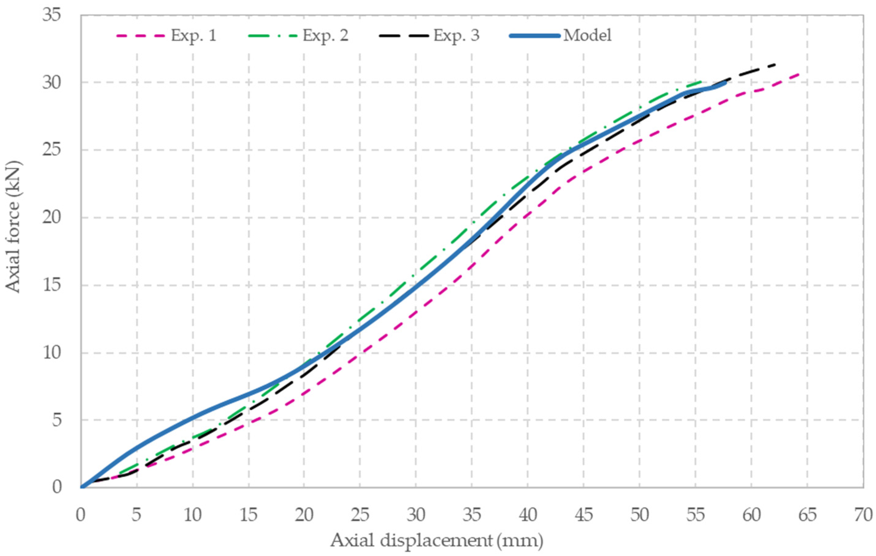
The model’s predictions have been compared with the published experimental data [9,15] obtained from static in-plane tensile load tests on mesh panels of dimensions 320 × 580 mm, with 80 × 100 mm hexagonal double-twisted cells and a 2.7 mm wire diameter. In these tests, the wire mesh panel was subjected to a uniform tensile load along the top edge at a constant loading rate of 10 mm/min. The lower edge of the panel was fully restrained, and an additional four points (near the vertical sides) were restrained from horizontal movement. In the model, additional constraints were imposed at the ends of wires to prevent them from unravelling, as shown in Figure 8.
The vertical reaction force at the lower edge is plotted against the displacements of the upper edge for three experiments, as shown in Figure 9. The model overestimates the reaction force at the initial stage of the test, but this is almost certainly due to initial slackness before the full engagement of the mesh. The numerical model is in excellent agreement with the data thereafter.
A more challenging test of the model is provided by comparing its predictions with those obtained from out-of-plane experimental tests reported in the literature [10,18,20]. In Ref. [10], a 3 × 3 m mesh panel with 80 × 100 mm hexagonal double-twisted cells manufactured from 3 mm diameter wire (P8/3) was supported horizontally by a rigid structure, and fully constrained on all four edges. The panel was subjected to vertical load by a hemi-spherical plate which was placed underneath the centre of the panel and pulled upwards at a constant velocity of 10 mm/s. The loading was continued until the onset of material damage.
In Figure 10, the model prediction of the deformation of the panel is shown in a state of maximum deformation, just before the onset of material failure.
The experimental data and the model’s predictions of vertical reaction force to the vertical displacement at the top of the spherical plate are plotted in Figure 11. The results show that the model satisfactorily predicts the load–deformation response of the panel.
For comparison purposes, the model’s predictions for a 2.7 mm diameter wire mesh is also shown in Figure 11. As expected, this mesh responds more flexibly to the load.
3.2. Dynamic Impact Loading Tests
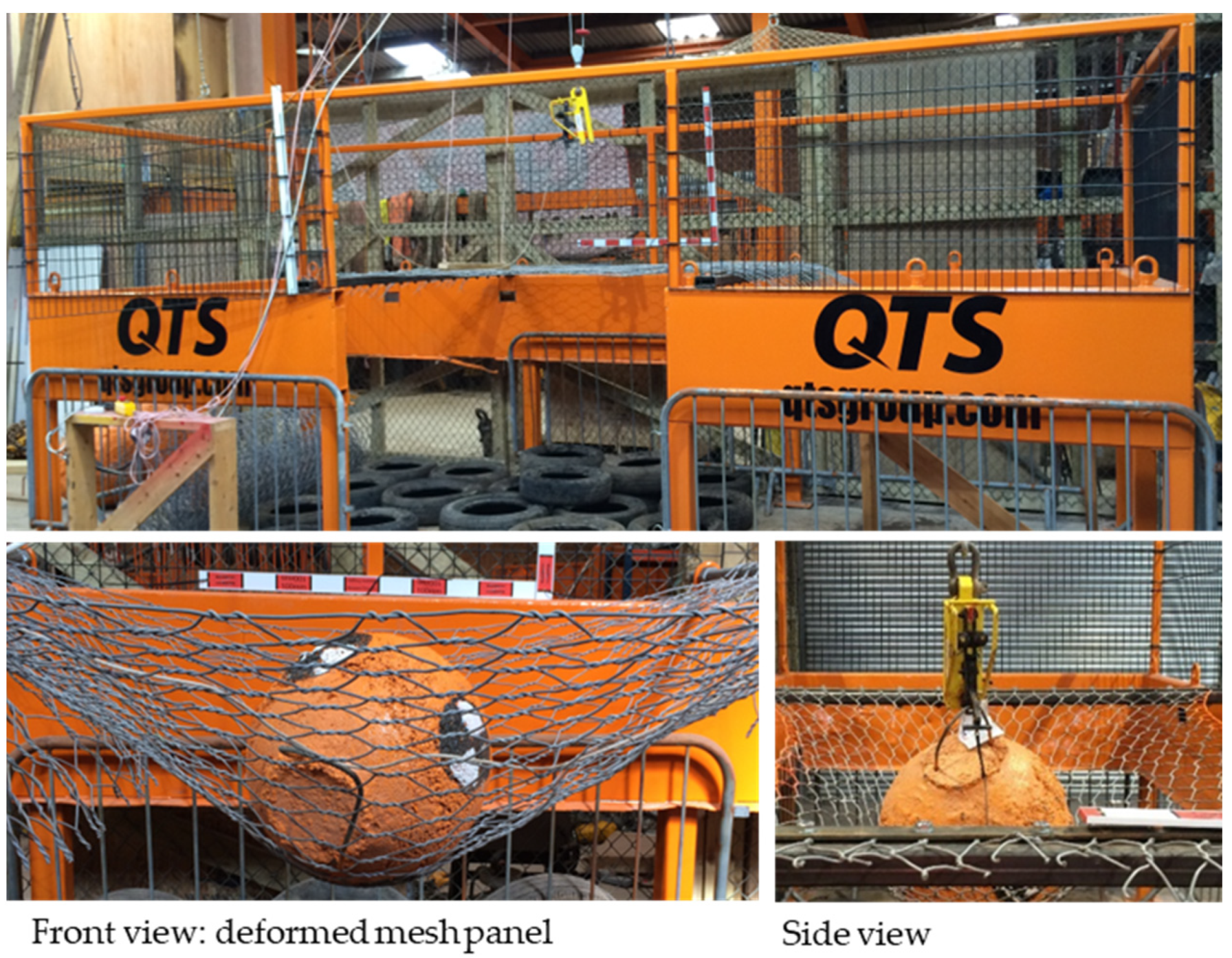
In general, impact tests are conducted by dropping masses onto wire meshes that are fully constrained on all four sides [5,8,9,10]. This test arrangement over-constrains the wire mesh and cannot reproduce the response of wire meshes in the field, where they are strongly constrained by the posts but only partially restrained longitudinally by wire ropes (Figure 2). To overcome this limitation, in this study, an impact testing rig was designed and used to laterally test the constrained wire mesh panels under more realistic conditions, as shown in Figure 12 and Figure 13.
Various panel lengths and boulder masses were employed. The test rig has two adjustable horizontal crossbeams which support the panel, and a high-speed camera (500 fps) is used to capture the boulder velocity and the wire mesh deformation. Two additional cameras are used to record the lateral deformation of the panel and the deflection of the supporting beams.
In this paper, we report test data obtained from impact tests conducted using spherical concrete “boulders” of 100 kg mass (test 1) and 200 kg mass (test 2) on 2 × 2 m wire mesh panels. The boulders were lifted to a height of 2.5 m above the mesh, which produced a velocity of 7 m/s at impact. The camera data were collected and analysed using Tracker, a video analysis and modelling tool [21].
In the literature, self-weight deflection has been modelled using pre-tension loads [9], but this may introduce unwanted side effects. Here, we impose the gravitational force in the model prior to the impact load. The boulders are modelled as rigid bodies, and the Abaqus contact algorithm is used to simulate the interaction between rigid and deformable bodies.
Figure 14 shows a comparison between measured and simulated displacements for these two tests. The model effectively reproduces the vertical response of the masses during the first impact and beyond. The accuracy of the model is reinforced by the observation that the rebound, and even the subsequent impact, are also well captured by the algorithm.
A comparison between the experimental data and the numerical predictions for the boulders’ velocities is shown in Figure 15a. Again, they are in excellent agreement. From these data, the kinetic energy of the masses can be readily determined (Figure 15b), which shows how the kinetic energy of the masses changes over time. Both masses are first brought to rest in approximately 0.1 s. The results shown in Figure 14 and Figure 15 are interesting in that they demonstrate that the mesh panels cannot be modelled as linear springs, since otherwise the maximum deflections (and time to peak deflection) would differ by a factor of √2.
4. Conclusions
Modelling double-twisted wire meshes with simplified geometries undermines the deformation modes and interactions that occur between wires in double-twisted sections. In addition, the constitutive models used for single steel wires cannot reproduce their real stress–strain relations. Here, direct modelling approach to wire mesh is considered; it obtained good agreement between the experimentally observed responses to static and impact loadings and the model. This result offers the prospect of exploring alternative catch fence designs in the search for improved efficiency. The model represents an initial step toward studying the effect of interactions between wires in double-twisted sections on the wire mesh’s response. In addition, further investigation into the material failure model, based on destructive testing, is recommended.
Author Contributions
Writing—original draft, H.A.-B.; Writing—review & editing, Z.G.; Supervision, A.S. All authors have read and agreed to the published version of the manuscript.
Funding
This research was funded by The Knowledge Transfer Partnerships (KTP) programme of the Innovate UK (Project number: 9980) and QTS Group Ltd., a leading railway infrastructure services company in the UK (http://www.qtsgroup.com/ (accessed on 7 June 2023)).
Data Availability Statement
The data presented in this study are available on request from the corresponding author. The data are not publicly available due to commercial restrictions.
Acknowledgments
We acknowledge the use of the laboratory and high-performance computing facilities provided by the School of Engineering, University of Glasgow. The technical contribution to this work by Simon Wheeler and Trevor Davies of the University of Glasgow is also acknowledged.
Conflicts of Interest
The authors declare no conflict of interest.
References
- Foster, C.; Pennington, C.; Culshaw, M.G.; Lawrie, K. The national landslide database of Great Britain: Development, evolution and applications. Environ. Earth Sci. 2011, 66, 941–953. [Google Scholar] [CrossRef] [Green Version]
- Network Rail UK. West of Exeter Route Resilience Study. 2014. Available online: https://www.networkrail.co.uk/wp-content/uploads/2016/11/West-of-Exeter-Route-Resilience-Study.pdf (accessed on 3 February 2023).
- Etag, E.O.T.A. Guideline for European technical approval of falling rock protection kits. Eur. Organisat. Techn. Appr. 2008, 27. [Google Scholar]
- Gerber, W. Guideline for the Approval of Rockfall Protection Kits; Swiss Agency for the Environment, Forests and Landscape (SAEFL); Swiss Federal Research Institute WSL: Birmensdorf, Switzerland, 2001. [Google Scholar]
- Buzzi, O.; Spadari, M.; Giacomini, A.; Fityus, S.; Sloan, S.W. Experimental Testing of Rockfall Barriers Designed for the Low Range of Impact Energy. Rock Mech. Rock Eng. 2013, 46, 701–712. [Google Scholar] [CrossRef]
- Muraishi, H.; Samizo, M.; Sugiyama, T. Development of a Flexible Low-Energy Rockfall Protection Fence. Q. Rep. Railw. Tech. Res. Inst. 2005, 46, 161–166. [Google Scholar] [CrossRef]
- Al-Budairi, H.; Gao, Z.; Steel, A.; Wheeler, S.; Davies, T. Modelling and optimising of a light-weight rockfall catch fence system. In Proceedings of the NAFEMS UK Conference, Telford, UK, 15–16 June 2016; pp. 129–132. [Google Scholar]
- Gentilini, C.; Gottardi, G.; Govoni, L.; Mentani, A.; Ubertini, F. Design of falling rock protection barriers using numerical models. Eng. Struct. 2013, 50, 96–106. [Google Scholar] [CrossRef]
- Thoeni, K.; Lambert, C.; Giacomini, A.; Sloan, S.W. Discrete modelling of hexagonal wire meshes with a stochastically distorted contact model. Comput. Geotech. 2013, 49, 158–169. [Google Scholar] [CrossRef]
- Bertrand, D.; Nicot, F.; Gotteland, P.; Lambert, S. Discrete element method (DEM) numerical modeling of double-twisted hexagonal mesh. Can. Geotech. J. 2008, 45, 1104–1117. [Google Scholar] [CrossRef]
- Escallón, J.; Wendeler, C.; Chatzi, E.; Bartelt, P. Parameter identification of rockfall protection barrier components through an inverse formulation. Eng. Struct. 2014, 77, 1–16. [Google Scholar] [CrossRef]
- Van Tran, P.; Maegawa, K.; Fukada, S. Experiments and Dynamic Finite Element Analysis of a Wire-Rope Rockfall Protective Fence. Rock Mech. Rock Eng. 2013, 46, 1183–1198. [Google Scholar] [CrossRef]
- Bertrand, D.; Trad, A.; Limam, A.; Silvani, C. Full-Scale Dynamic Analysis of an Innovative Rockfall Fence Under Impact Using the Discrete Element Method: From the Local Scale to the Structure Scale. Rock Mech. Rock Eng. 2012, 45, 885–900. [Google Scholar] [CrossRef]
- Nicot, F.; Cambou, B.; Mazzoleni, G. From a constitutive modelling of metallic rings to the design of rockfall restraining nets. Int. J. Numer. Anal. Methods Géoméch. 2001, 25, 49–70. [Google Scholar] [CrossRef]
- Mentani, A.; Giacomini, A.; Buzzi, O.; Govoni, L.; Gottardi, G.; Fityus, S. Numerical Modelling of a Low-Energy Rockfall Barrier: New Insight into the Bullet Effect. Rock Mech. Rock Eng. 2016, 49, 1247–1262. [Google Scholar] [CrossRef]
- Lambert, S.; Bertrand, D.; Berger, F.; Bigot, C. Low energy rockfall protection fences in forested areas: Experiments and numerical modelling. In Proceedings of the International Conference on Structures under Shock and Impact (SUSI Congress), Kyoto, Japan, 25 May 2009; pp. 133–138. [Google Scholar]
- Abaqus Analysis User’s Manual; Version 6.14; Dassault Systems Simulia Corp.: Providence, RI, USA, 2014.
- Maccaferri Technical Data Sheet for Rockfall Netting. 2015. Available online: https://www.geofabrics.co/sites/default/files/technicaldata/tds-dtnet-pvc-gl-may-2015.pdf (accessed on 3 February 2023).
- SolidWorks; Version 2016; Dassault Systèmes SolidWorks Corp.: Waltham, MA, USA.
- UNI 11437:2012; Rockfall Protective Measures: Tests on Meshes for Slope Coverage. UNI Nazionale Italiano di Unificazione: Milano, Italy, 2012.
- Tracker Video Analysis and Modelling Tool. Version 4.96. Available online: http://physlets.org/tracker/ (accessed on 3 February 2023).
Figure 1.
Number of major rockfalls in the UK, as recorded by the BGS [1].
Figure 1.
Number of major rockfalls in the UK, as recorded by the BGS [1].

Figure 2.
Components of a low-energy rockfall catch fence.

Figure 3.
A single cell in a double-twisted hexagonal wire mesh.

Figure 4.
Geometrical representations of a double-twisted hexagonal wire mesh.

Figure 5.
Geometric modelling of a double-twisted hexagonal wire mesh panel.

Figure 6.
Uniaxial tensile tests on single wire specimens of double-twisted hexagonal mesh.

Figure 7.
Uni-axial elastic–plastic material response, with progressive damage.


Figure 9.
Comparison between experimental data [9,15] and the numerical model for uniaxial loading of a wire-mesh panel.

Figure 10.
Model simulation of punching test on a wire mesh panel [10].
Figure 10.
Model simulation of punching test on a wire mesh panel [10].

Figure 11.
Comparison between experimental [10] and predicted load–displacement data for a punching test.
Figure 11.
Comparison between experimental [10] and predicted load–displacement data for a punching test.

Figure 12.
Schematic of the impact test rig.

Figure 13.
The test rig with front and side views of the boulder after impact.

Figure 14.
Comparison between experimental and numerical data for vertical displacements.

Figure 15.
Comparison between experimental and numerical data for (a) vertical velocity and (b) kinetic energy.
Figure 15.
Comparison between experimental and numerical data for (a) vertical velocity and (b) kinetic energy.


Disclaimer/Publisher’s Note: The statements, opinions and data contained in all publications are solely those of the individual author(s) and contributor(s) and not of MDPI and/or the editor(s). MDPI and/or the editor(s) disclaim responsibility for any injury to people or property resulting from any ideas, methods, instructions or products referred to in the content. |
© 2023 by the authors. Licensee MDPI, Basel, Switzerland. This article is an open access article distributed under the terms and conditions of the Creative Commons Attribution (CC BY) license (https://creativecommons.org/licenses/by/4.0/).
Share and Cite
MDPI and ACS Style
Al-Budairi, H.; Gao, Z.; Steel, A. Numerical Modelling of Double-Twisted Wire Mesh for Low-Energy Rockfall Catch Fences. Geosciences 2023, 13, 180. https://doi.org/10.3390/geosciences13060180
AMA Style
Al-Budairi H, Gao Z, Steel A. Numerical Modelling of Double-Twisted Wire Mesh for Low-Energy Rockfall Catch Fences. Geosciences. 2023; 13(6):180. https://doi.org/10.3390/geosciences13060180
Chicago/Turabian StyleAl-Budairi, Hassan, Zhiwei Gao, and Andrew Steel. 2023. "Numerical Modelling of Double-Twisted Wire Mesh for Low-Energy Rockfall Catch Fences" Geosciences 13, no. 6: 180. https://doi.org/10.3390/geosciences13060180
Note that from the first issue of 2016, this journal uses article numbers instead of page numbers. See further details here.